background image

29

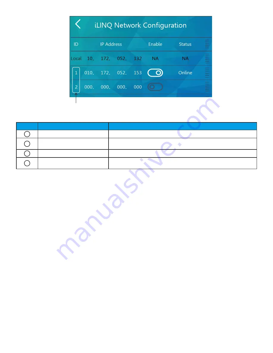
Figure 31 - iLINQ Network Configuration Page

Item # Item

Description

1

Local Controller

IP address of the local controller

2

Configured Remote Controller

A configured remote controller that has been enabled on the iLINQ 

network with no communication error

3

Unconfigured Remote Controller An unconfigured remote controller slot

4

iLINQ Network Node Address

iLINQ network addresses, 1-9. The node address determines the order of 

the iLINQ summary pages

6.3 

iLINQ Network Summary Pages

The iLINQ network summary pages display key data points for each remote controller enabled on the iLINQ network 

configuration page. To access the iLINQ network summary pages, first, enable the “Display iLINQ” item on the display 

settings page. The summary pages can then be accessed by tapping the iLINQ icon on the home page or detail page. 

The first iLINQ summary page displayed belongs to the local controller. The following summary pages belong to the 

remote controllers and are populated in order by iLINQ network node address. The number of summary pages available 

is indicated by the number of navigation tabs on the bottom of the summary page and corresponds to the number of 

node addresses configured and enabled on the iLINQ network configuration page. To navigate between summary pages, 

swipe in either direction on the screen or use the page navigation tabs at the bottom of the screen. All sensor values are 

displayed on the iLINQ network summary pages. If a sensor is not installed, dashes are shown in place of a valid sensor 

value. 

Summary of Contents for iLINQ Room Terminal

Page 1: ...damage arising from improper service or service procedures If you service this unit you assume responsibility for any injury or property damage which may result In addition in jurisdictions that requ...

Page 2: ...DDC Controller 11 4 iLINQ System Configuration 12 4 1 Space Temperature and Space Humidity Source Room Terminal 12 4 2 Space Temperature and Space Humidity Source Onboard LCD 12 4 3 Space Temperature...

Page 3: ...ernet Port Configuration Page 25 5 10 1 Overview 25 5 11 Wi Fi Hotspot Page 26 5 12 Controller Display Emulator Page 26 5 12 1 Overview 26 5 13 iLINQ Network Page 27 5 14 Room Terminal System Informat...

Page 4: ...cription 0130L00292 Room Terminal Onboard temperature humidity sensor touchscreen LCD and Wi Fi hotspot 0163L00300 Surface Mount Mounting bracket for installing the room terminal on the surface of a w...

Page 5: ...ption 0130L00292 1 iLINQ Room Terminal 0163L00299 1 Flush Mount Enclosure 0163L00301 1 Frame 0130L00293 1 Power Supply N A 2 Wires Fork Terminal Stripped Terminal B1096102 2 Wire Ties iLINQ Room Termi...

Page 6: ...nsmits and receives data to and from the iLINQ controller via 3 wire serial communication The space temperature and humidity is included in this data transmission For this reason the room terminal ins...

Page 7: ...must be referenced 2 1 Components and Specifications The iLINQ Room Terminal application is designed specifically to function with the hardware described in this section 2 1 1 Room Terminal 0130L0029...

Page 8: ...installed in the RTU s control box and uses the 24VAC from the factory installed control transformer as the input power The 24VDC output is used to power the room terminal The Power Supply output is...

Page 9: ...4 VDC 16 20 AWG 1 4 Strip Length torque screws to 7 lbf X in installer supplied wires Serial Communication Shielded Three Conductor 20 22 AWG 1 4 Strip Length Ground shield at iLINQ DDC J11 GND as sho...

Page 10: ...nal enclosure must meet the following requirements In the space served by the RTU In On the wall approximately 4 feet above the finished floor Avoid heat sources such as radiators or direct sunlight A...

Page 11: ...en the power supply and other components Peel the backing off the adhesive mounting tape and attach the power supply to the control box POWER SUPPLY 24 VAC SOURCE POWER SUPPLY 24 VAC SOURCE Figure 5 S...

Page 12: ...Press and hold 2 Press and enter Service Password Factory Default 1954 4 Press Controller Display 3 Press enter icon Figure 9 Room Terminal Configuration 4 2 Space Temperature and Space Humidity Sour...

Page 13: ...r and parameters If needed refer to the iLINQ User Manual for additional detail 5 1 User Interface Navigation The majority of the user interface is comprised of the following pages Home Page Detail Pa...

Page 14: ...LINQ controller 2 Space Humidity Space humidity from iLINQ controller 3 Date Time Date Time from iLINQ controller 4 Unit Number Unit number of iLINQ controller 5 Space CO2 CO2 value from iLINQ control...

Page 15: ...e icon is displayed on the home page To override the occupancy press and hold the icon An option to password protect the occupancy override is available on the display settings page If enabled the use...

Page 16: ...o display the space CO2 and iLINQ summary page link is available on the display settings page 5 3 2 Mode of Operation The current operating status of the iLINQ controller is displayed in the left pane...

Page 17: ...rminal and is normalized by the iLINQ controller i e Offsets etc When the up down arrows are pressed the space temperature setpoint adjust value is increased decreased Pressing the up button will resu...

Page 18: ...d 4 Graph Duration Displays menu with the following selectable options for the range of the X axis 1 min 5 min 10 min 5 Refresh Reset line graph and variable visibility 6 Historical Trend Link to hist...

Page 19: ...e plot color of the variables plotted in the graphing window Tap the variable to show hide its line plot in the graphing window To toggle the visibility of the legend tap the show hide legend icon 5 6...

Page 20: ...n of the time stamp in the graphing window 5 6 3 Graphing Window When the historical trend page loads the historical line plots for each variable populate the graphing window The current time is shown...

Page 21: ...larm Enabled Enabled or Disabled Magenta Dehumidification No Alarm Enabled Enabled or Disabled Blue Force No Alarm Enabled Enabled or Disabled Yellow Off Alarm Enabled Enabled Flashing Red Ventilation...

Page 22: ...o access to the service page Tap the password field enter the iLINQ service password and tap the check mark to confirm the entered password If needed tap the eye icon to view the current password ente...

Page 23: ...ge Link Configure network properties of the iLINQ room terminal s Ethernet port 3 Wi Fi Hotspot Page Link Enable Disable and configure Wi Fi hotspot 4 Controller Display Page Link Emulator of the iLIN...

Page 24: ...seconds LCD backlight delay off timer in seconds Timer resets when the screen is touched If off the LCD backlight turns on when screen is touched If set to 0 the backlight remains on with no timeout n...

Page 25: ...gs are assigned to the room terminal automatically by a DHCP server If disabled the IP settings must be configured manually MAC Address N A N A Media access control address read only IP Address 0 0 0...

Page 26: ...r an extended amount of time during occupied hours Refer to the iLINQ DDC User Manual for additional information about the onboard LCD 5 12 1 Overview Figure 28 Controller Display Page Item Item Descr...

Page 27: ...ble Press and drag in the table area to scroll through the data 5 14 1 Overview Figure 29 Room Terminal System Information Page Item Description Software Version Daikin software application version Op...

Page 28: ...are for example only and are subject to change to meet installation requirements For controller identification purposes it is recommended that each iLINQ DDC Controller is assigned a unique Unit Numb...

Page 29: ...st enable the Display iLINQ item on the display settings page The summary pages can then be accessed by tapping the iLINQ icon on the home page or detail page The first iLINQ summary page displayed be...

Page 30: ...te iLINQ controller CO2 Value of space CO2 from remote iLINQ controller Date Time Date Time from the local controller Supply Temperature value of the supply temperature sensor from the remote iLINQ co...

Page 31: ...esses to it s clients in the range of 172 27 72 100 to 172 27 72 199 Refer to Figure 33 for an example of proper network settings The IP settings are for example only and are subject to change to meet...

Page 32: ...e WPA PSK NONE None no access protection for Wi Fi hotspot WPA PSK Wi Fi Protected Access Pre Shared Key needed to access the Wi Fi hotspot Password Minimum 8 Characters 12345678 Password required to...

Page 33: ...pot Figure 35 Wi Fi SSID Once connected to the Wi Fi hotspot enter 172 27 72 1 in the address bar of an internet browser to view the device discovery page The device discovery page lists each iLINQ co...

Page 34: ...ls on RTU 01 and RTU 04 A user at the RTU 01 room terminal may view change settings in RTU 01 and can view status information for the other units configured in the iLINQ Network settings for RTU 01 Fi...

Page 35: ...earance Description Back Button Tap to return to previous page Keypad Tap to enter a string of characters tap check mark to apply Toggle Switch Enabled Disabled Tap to enable disable settings Units Ro...

Page 36: ...n the room terminal display Verify serial communication polarity and connection are correct per the diagram in the wiring specifications section Verify iLINQ controller s software version is 1 3 or gr...

Reviews: