Timer
Identification code
Description
Schedule timer
DST301BA51
Controller with schedule
timing functionality.
Valves
Identification code
Description
2-way valve (ON/OFF type)
EKMV2C09B7
Electronic 2-way valve to
control the water supply.
3-way valve (ON/OFF type)
EKMV3C09B7
Electronic 3-way valve to
control the water supply.
Electronic circuits
Identification code
Description
Valve control PCB
EKRP1C11
Mandatory electronic circuit
when 2-way or 3-way valve
is used.
Optional PCB for MOD-bus
connection
EKFCMBCB7
Electronic circuit with MOD-
bus interface connections.
Wiring adaptor for electrical
appendices
KRP4A(A)53
KRP2A52
Electronic circuit with
additional connections for
external input/output signals.
Remote “ON/OFF” and
“Forced OFF” kit
EKROROA
Connection to control the
ON/OFF operation remotely.
FWF
Fan coil units
4PW64524-1 – 09.2010
Installation manual
5
3 Prepare the installation of the fan coil unit
Verify the appropriate installation location
3.2
Verify the appropriate installation location
When selecting the installation location, take into account the instructions as mentioned in
the following paragraphs of this chapter.
Select an installation location where the following conditions are fulfilled:
■
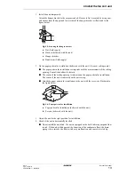
the space around the unit is adequate for maintenance and servicing. See figure
“Space
required for installation” on page 6
.
■
the space around the unit allows sufficient air circulation and air distribution. See figure
“Space required for installation” on page 6
.
■
the unit may be installed on ceilings up to 3.5 m. However, it becomes necessary to make
field settings using the remote controller when installing the unit at a height over 2.7 m.
Install the unit where the height of the decoration panel is more than 2.5 m to avoid
accidental touching.
■
the air passage is not blocked.
■
the condensate water can be properly drained.
■
the installation location is frost-free.
■
the unit can be installed horizontally.
Summary of Contents for FWF02B7TV1B
Page 39: ...NOTES...


