Information
The equipment described in this manual may cause electronic noise generated from
radio-frequency energy. The equipment complies to specifications that are designed
to provide reasonable protection against such interference. However, there is no
guarantee that interference will not occur in a particular installation.
It is therefore recommended to install the equipment and electric wires keeping
proper distances away from stereo equipment, personal computers, etc.
In extreme circumstances a distance of 3 m or more is required.
Installation manual
8
FWF
Fan coil units
4PW64524-1 – 09.2010
3 Prepare the installation of the fan coil unit
Electrical characteristics
Model
FWF
Phase
1N~
Frequency (Hz)
50
Voltage range (V)
220-240
Voltage tolerance (V)
±10%
Maximum running current (A)
0.9
Overcurrent fuse (A) (field supply)
16
(a)
Table 3.2: Electrical characteristics
(a)
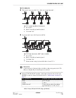
In case of common power supply to more than one unit (as illustrated in figure
“Group control or use with 2
remote controllers” on page 19
), keep total current of interconnection wiring between units less than 12 A.
Branch the line outside the terminal block of the unit in accordance with electrical equipment standards, when
using two power wires of a gauge greater than 2 mm². The branch must be sheathed in order to provide an equal
or greater degree of insulation as power supply wiring itself.
Specifications for field wiring
Wire
Size (mm²)
Length
Power supply wiring
H05VV-U3G
(a),(b)
According to the
applicable
legislation. Max. 4.0
—
Remote controller
and unit transmission
wiring
Sheathed wire
2 conductors
(c)
0.75-1.25
Max. 500 m
(d)
Table 3.3: Field wiring specifications
(a)
Only in case of protected pipes. Use H07RN-F in case of no protection.
(b)
Run electrical wiring through a conduit to protect against external forces.
(c)
Use double insulation wire for remote controller (sheath thickness:
≥
1 mm) or run wires through a wall or
conduit so that the user cannot come in contact with them.
(d)
This length is the total extended length in the system in case of group control. See figure
“Group control or use
with 2 remote controllers” on page 19
.
Prepare the installation of optional equipment
Summary of Contents for FWF02B7TV1B
Page 39: ...NOTES...


