


■
English
10
Indoor Unit Installation (1)
4-2. Installation
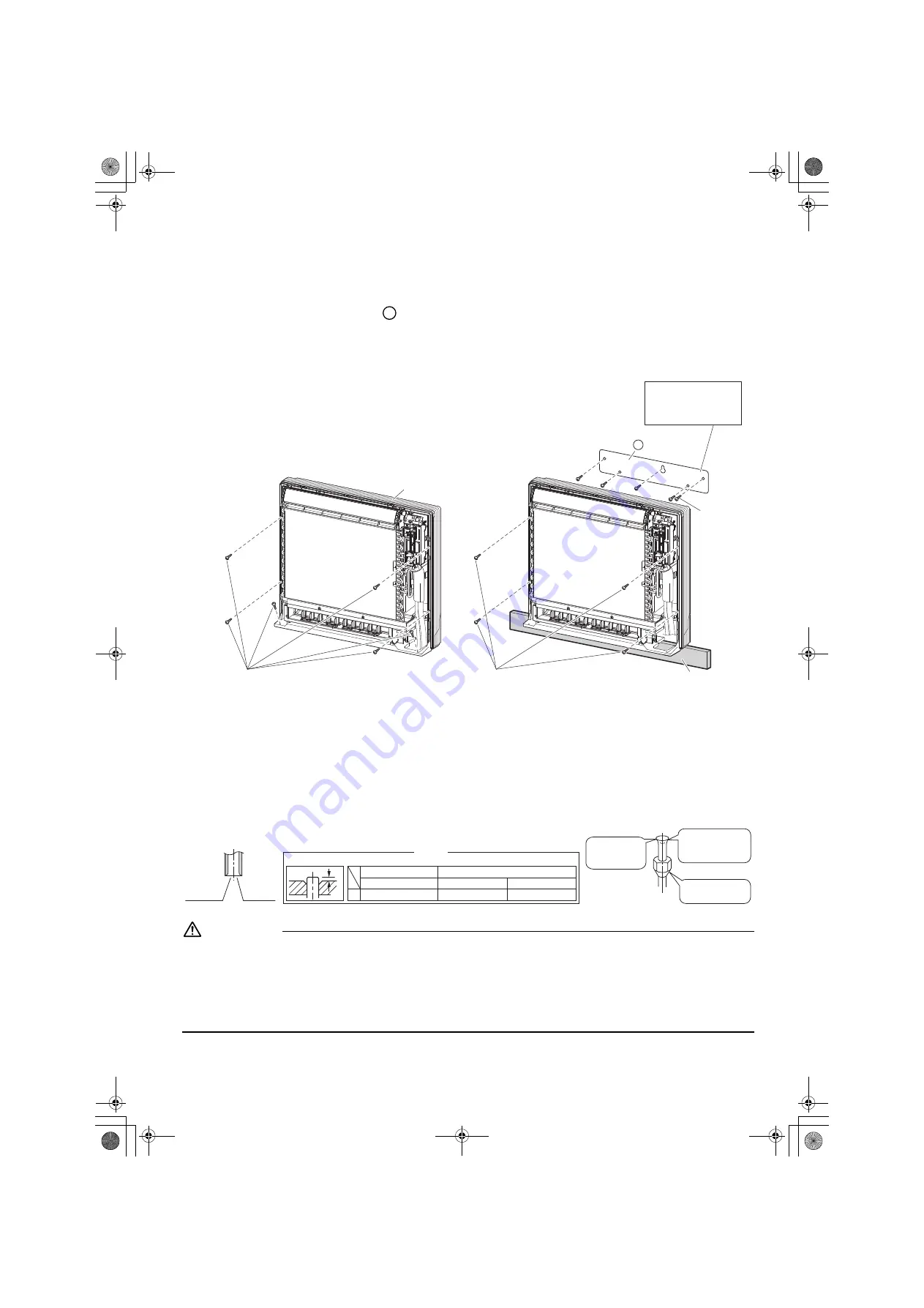
• Secure using 6 screws for floor installations. (Do not forget to secure to the rear wall.)
• For wall installations, secure the
mounting plate using 5 screws and the indoor unit using 4 screws.
• The mounting plate should be installed on a wall which can support the weight of the indoor unit.
1) Temporarily secure the mounting plate to the wall, make sure that the panel is completely level, and mark the boring
points on the wall.
2) Secure the mounting plate to the wall with screws.
3) Once refrigerant piping and drain piping connections are complete, fill in the gap of the through hole with putty.
A gap can lead to condensation on the refrigerant pipe, and drain pipe, and the entry of insects into the pipes.
4) Attach the front panel and front grille in their original positions once all connections are complete.
5.
Flaring the pipe end
1) Cut the pipe end with a pipe cutter.
2) Remove burrs with the cut surface facing downward so that the chips do not enter the pipe.
3) Fit the flare nut on the pipe.
4) Flare the pipe.
5) Check that the flaring is properly made.
WARNING
1) Do not use mineral oil on flared part.
2) Prevent mineral oil from getting into the system as this would reduce the lifetime of the units.
3) Never use piping which has been used for previous installations. Only use parts which are delivered with the unit.
4) Do never install a drier to this R410A or R32 unit in order to guarantee its lifetime.
5) The drying material may dissolve and damage the system.
6) Protect or enclose the refrigerant tubing to avoid mechanical damage.
7) Incomplete flaring may cause refrigerant gas leakage.
A
Casing
6 screws (M4 × 25L)(Field supply)
Floor Installation
Wall Installation
4 screws (M4 × 25L)(Field supply)
5 screws
(M4 × 25L)
(Field supply)
Mounting plate
A
Molding
The mounting plate
should be installed on a
wall which can support the
weight of the indoor unit.
Flare’s inner
surface must
be scratch-free.
The pipe end must
be evenly flared in
a perfect circle.
Make sure that the
flare nut is fitted.
Set exactly at the position shown below.
A
Flaring
Die
A
0-0.5mm
Clutch-type
Flare tool for R410A / R32
1.0-1.5mm
Clutch-type (Ridgid-type)
1.5-2.0mm
Wing-nut type (Imperial-type)
Conventional flare tool
(Cut exactly
at right
angles.)
Remove
burrs
3PEN477070-1A.book Page 10 Tuesday, March 28, 2017 10:01 AM