background image

8

English

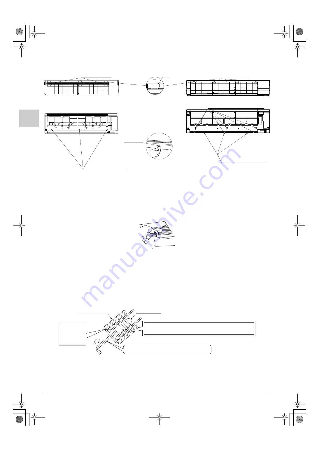
(2) Remove the front grille.

< How to attach the front grille (for 100 class only) >

Attach the screw cover (6) provided with the air outlet. (3 places)

Remove the drain plug, the insulation tubing, and the drain hose from the drain pan and replace. 

(Refer to Fig. 9)

Mold the local refrigerant piping ahead of time, matching it to the liquid pipe and gas pipe marks 
engraved on the installation panel (1).

< Replacing the drain hose and drain plug >

(1) Remove the drain plug and insulating tube.
(2) Remove the drain hose installation screws, and pull out the drain hose.
(3) Replace the drain plug and the insulating tube onto the right side.
(4) Replace the drain hose onto the left side, and secure the hose with the installation screws.

If the drain hose is not replaced, water is likely to be accumulated inside the unit. The occurrence of slime may 
clog the hose and cause water leakage.

Tab position 
(3 places)

Tab position 
(4 places)

Screw position (6 places)

Screw position 
(3 places)

Grille clamp 
positions (3 places)

Fig. 8

Tab

Front grille securing positions 
for 71 class

Front grille securing positions 
for 100 class

How to remove 
grille clamps 
(for 100 class only)

Remove the clamps 
under the front grille 
with a coin.

Coin, etc.

Drain plug

Insulating tube

Fig. 9

Do not place lubricant (refrigerant oil) when inserting. 
This may cause deterioration and water leaks.

Insert using a hexagon wrench (4mm).

Make sure 
there are 
no gaps.

3P184443-9J_FM6.book  Page 8  Wednesday, December 14, 2011  10:29 AM

Summary of Contents for FAQ71CVEB

Page 1: ...LAR GUARDE ESTE MANUAL EN UN LUGAR A MANO PARA LEER EN CASO DE TENER ALGUNA DUDA PRIMA DELL INSTALLAZIONE LEGGERE ATTENTAMENTE QUESTE ISTRUZIONI TENERE QUESTO MANUALE A PORTATA DI MANO PER RIFERIMENTI...

Page 2: ...in property damage or personal injury which may be serious depending on the circumstances After completing installation conduct a test operation to confirm that the equipment operates without any pro...

Page 3: ...Toxic gas may be produced if the refrigerant comes into contact with fire After completing installation check for refrigerant gas leakage Toxic gas may be produced if the refrigerant gas leaks into th...

Page 4: ...ent in the air is high such as beachfront or where the voltage fluctuates such as factories or where the base vibrates such as automobiles or marine vessels 2 2 ACCESSORIES Check the following accesso...

Page 5: ...g the air outlet or inlet of either the indoor or outdoor units It may result in insufficient cooling or heating This can lead to malfunction or decreased per formance due to decreased air volume Are...

Page 6: ...nce can be ensured Refer to Fig 1 and Fig 2 Where condensate can be properly drained Where pipe between indoor and outdoor units is possible within the allowable limit Refer to the installation manual...

Page 7: ...llation panel 1 to the wall using the attachment screws for the installation panel 2 or bolts If using bolts attach the panel with a M8 or M10 bolt on both sides for a total of 2 bolts If dealing with...

Page 8: ...main unit and remove You can also remove it by sliding the front panel either to the left or right and pulling it forward 3 Remove the screw from the control box lid and pull the handle forward 2 Poi...

Page 9: ...e the drain hose onto the left side and secure the hose with the installation screws If the drain hose is not replaced water is likely to be accumulated inside the unit The occurrence of slime may clo...

Page 10: ...rant pipe with vinyl tape Seal the piping through hole with putty corking material Refrigerant pipe Be sure to pass all wires through the wiring guide Tab There are 2 places for 71 class There are 3 p...

Page 11: ...rve the following precaution For flare connection use dedicated pipe cutter and flaring tools for R410A Apply ester oil or ether oil to the inside of the flare section before connecting Use the flare...

Page 12: ...piping insulation tubing and insulating tape 3 The insulating tape 3 should be wrapped from the L shaped bend all the way to the end inside the unit Refer to Fig 15 When brazing the refrigerant pipin...

Page 13: ...e of refrigerant due to air purge or forgetting the additional refrigerant charge may cause malfunc tion of the unit does not sufficiently cool or heat For installation of refrigerant piping be sure t...

Page 14: ...nual provided with the drain up kit 2 Make sure the drain works properly After drain piping work is complete perform a drain check by opening the front panel removing the air filter pouring water into...

Page 15: ...earth wires or lightning rods might cause abnormally high electric potential in the earth dur ing lighting storms For electric wiring work refer also to WIRING DIAGRAM attached to the inside of the fr...

Page 16: ...s not to leave any gap and prevent entry of small creatures from outside Route the low voltage wires remote controller wiring 50mm or more away from the high voltage wires interconnecting wires betwee...

Page 17: ...e terminal screws If the blade of screwdriver is too small the head of the screw might be damaged and the screw will not be properly tightened If the terminal screws are tightened too hard screws migh...

Page 18: ...r to Fig 28 NOTE Terminal numbers of outdoor and indoor units must agree P1 P2 1 2 3 P1 P2 1 2 3 Main power supply Earth leakage circuit breaker Outdoor unit NOTE Indoor unit Remote controller Optiona...

Page 19: ...EOVER If BRC1E model remote controller is used see the manual attached to the remote controller If the remote controller is a wired one change the switch setting as follows 1 Insert a flat screwdriver...

Page 20: ...page 4 Make sure that the installation and wiring work for the indoor and outdoor units is all completed Make sure that the following items are all closed the control box lid of the indoor unit and t...

Page 21: ...me for the filter can be shortened depending on the usage environment Table 7 10 3 SETTING AIR FLOW RATE INCREASE MODE The set airflow rate HH H and L can be increased depending on the installation co...

Page 22: ...Perform field setting Refer to 10 1 to 10 4 for the master unit 3 Turn off the main power supply switch after 2 is finished 4 Detach remote controller from the master unit and connect it to the slave...

Page 23: ...heathed vinyl cord or cable 2 wire Gauge 0 75 1 25 mm 2 Length Max 100 m External terminal Contact that can ensure the minimum applicable load of 15 V DC 10 mA FORCED OFF ON OFF OPERATION Input ON sto...

Page 24: ...E FOR PROB LEMS After completing the test run press the INSPECTION TEST OPERATION button once to put the unit in inspection mode and make sure the malfunction code is 00 normal If the code reads anyth...

Page 25: ...normal and unit NO becomes 0 Then the display automatically changes from the inspection mode to the normal mode 11 2 MALFUNCTION CODE For places where the malfunction code is left blank the indicatio...

Page 26: ...unit H4 Low pressure switch failure Outdoor unit H7 Outdoor fan motor position signal malfunction Outdoor unit H9 Outdoor air thermistor system malfunction Outdoor unit Abnormal stop is applied depend...

Page 27: ...ting adapter failure to connect the adapter or the capacity is not set to the data retention IC U0 Suction pipe temperature abnormal Outdoor unit The refrigerant may be insufficient Abnormal stop is a...

Page 28: ...completed check that the control box lid the air filter and the suction grille are mounted In addition explain to the customer regarding the state ON OFF of the power supply breaker 12 WIRING DIAGRAM...

Page 29: ...BOARD CAPACITOR FLASHING LAMP SERVICE MONITOR GREEN MOTOR INDOOR FAN MOTOR SWING FLAP MOTOR SWING FLAP THERMISTOR AIR THERMISTOR COIL SELECTOR SWITCH EMERGENCY DIODE BRIDGE TERMINAL BLOCK REMOTE CONTR...

Page 30: ...1112 HT 3P184443 9L EM11A040A SP_00_CV_3P184443 9L fm Page 2 Thursday December 15 2011 3 27 PM...

Reviews: