D
–EIMAC00708-16EN - 30/76
Guidelines for ERAD E-SS/SL Installation
Design of condensing unit application, and, in particular, sizing of piping and piping path, is a responsibility of plant
designer. This paragraph is only focused to give suggestion to plant designer, this suggestions have to be weighted with
references to application peculiarities.
Condensing units are shipped with holding nitrogen charge. It is important to keep the unit tightly closed until th e remote
evaporator is installed and piped to the unit.
Installation of the refrigerant circuit must be done by a licensed technician and must comply with all relevant European
and national regulations.
It is the contractor’s responsibility to install the interconnection piping, leak test it and the entire system, evacuate the
system and supply the refrigerant charge.
All piping must be conformed to the applicable local and state codes.
Use refrigerant grade copper tubing only and isolate the refrigeration lines from building structures to prevent transfer of
vibration.
Do not use a saw to remove end caps. This might allow copper chips to contaminate the system. Use a tube cutter or
heat to remove caps. W hen sweating copper joints it is important to flow dry nitrogen through the system prior to
charging with refrigerant. This prevents scale formation and the possible formation of an explosive mixture of HFC -134a
and air. This will also prevent the formation of toxic phosgene gas, which occurs when HFC -134a is exposed to open
flame.
Soft solders are not to be used. For copper-to-copper joints use a phos-copper solder with 6% to 8% silver content. A
high silver content brazing rod must be used for copper-to-brass or copper-to-steel joints. Only use oxy-acetylene
brazing.
After the equipment is correctly installed, leak tested and evacuated , it can be charged with R134a refrigerant and
started under the supervision of Daikin authorized technician.
Refrigerant piping design
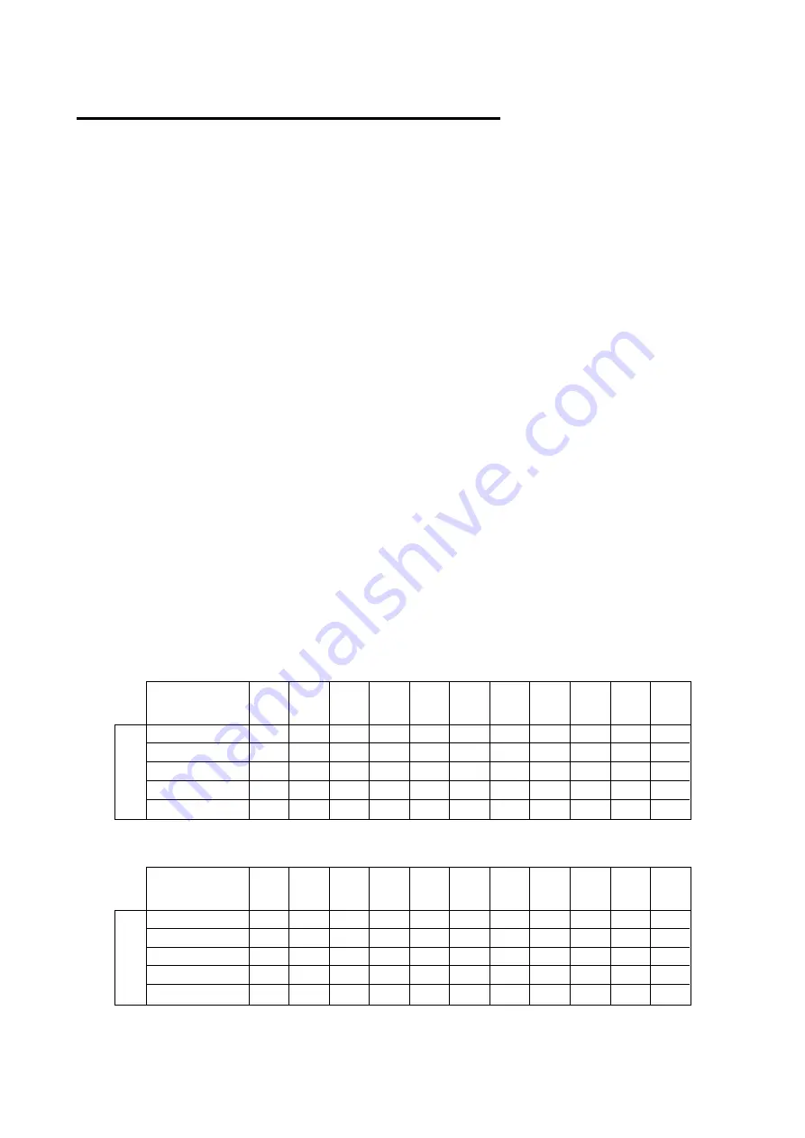
In order to minimize capacity loss, it is recommended to size the lines in such a way that the pressure drop of each line
does not result in an evaporating temperature decrease of more than 1°C.
Design of refrigeant piping depends on operating condition and, in particular, on evaporating temperature and suction
superheat, so values suggested in the following table have to be considered just as a reference; no claim may be
submitted to Daikin for wrong design of piping coming from the use of tables.
Table 12 - Recomandend maximum equivalent length (m) for Suction line
Full
Load
Cooling
Capacity (kW)
100
120
140
160
180
200
240
280
320
360
400
P
ip
in
g
S
iz
e
3" 1/8
100
80
60
50
40
30
23
17
13
10
9
2" 5/8
45
35
25
20
16
13
9
7
5
4
3
2" 1/4
15
12
9
7
6
5
3
2
2
1
1
1" 5/8
5
3
2
2
1
1
-
-
-
-
-
1" 3/8
2
1
1
1
-
-
-
-
-
-
-
Table 13 - Recomandend maximum equivalent length (m) for Liquid line
Full
Load
Cooling
Capacity (kW)
100
120
140
160
180
200
240
280
320
360
400
P
ip
in
g
S
iz
e
1" 5/8
-
-
250
200
175
140
100
75
60
45
40
1" 3/8
200
150
120
95
75
60
45
35
25
20
15
1" 1/4
80
60
45
35
25
20
15
12
10
8
6
7/8
20
15
12
9
7
6
4
3
3
-
-
3/4
10
7
5
4
3
3
-
-
-
-
-


