E(D/B)(H/L)Q011~016BB
Unit for air to water heat pump system
4PW67904-1 – 01.2011
Installation manual
14
■
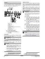
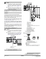
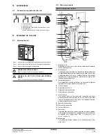
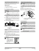
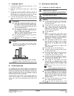
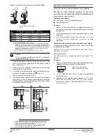
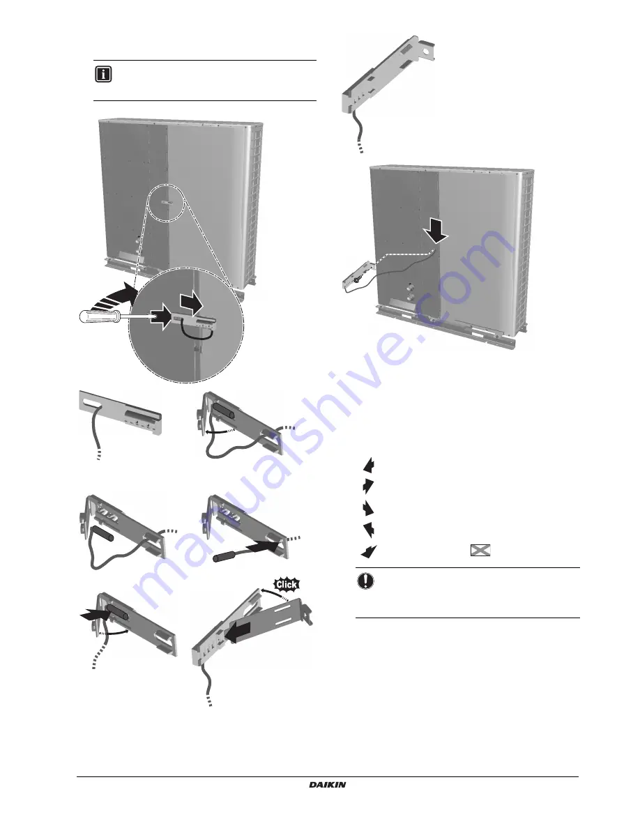
For E(D/B)L only. Follow the procedure as described below for
modifying the position of the air thermistor (R1T). The thermistor
fixture is delivered in the accessory bag.
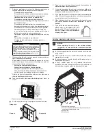
6.2.
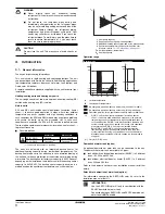
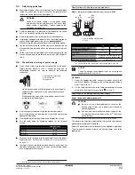
Installation servicing space
The numerical figures used in the figures represent the dimensions in
mm.
(Refer to
"6.4. Precautions on installation" on page 16
)
Precaution
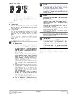
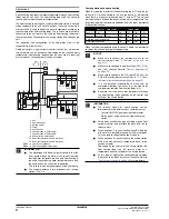
(A) In case of non-stacked installation
figure 1
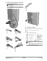
INFORMATION
Spare thermistor fixing plate is delivered in the
accessory bag.
2
1
3
4
5
6
8
7
9
10
Suction side obstacle
✓
Obstacle is present
Discharge side obstacle
1
In these cases, close the
bottom of the installation
frame to prevent the
discharged air from
being bypassed
Left side obstacle
Right side obstacle
2
In these cases, only
2 units can be installed.
Top side obstacle
This situation is not
allowed
NOTICE
Minimum distance B1 in
figure 1
mentions the space
required for correct operation of the unit. Required
space for servicing though is 300 mm.
11


