


PRODUCT DESIGN
20
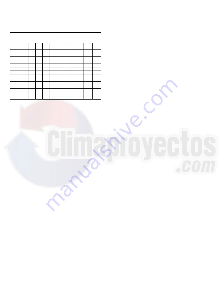
Sizing Between Single or Second Stage Regulator and Appliance*
Maximum Propane Capacities Listed are Based on 1/2" W.C. Pressure Drop at
11" W.C. Setting. Capacities in 1,000 BTU/HR
3/8"
1/2"
5/8"
3/4"
7/8"
1/2"
3/4"
1"
1-1/4"
1-1/2"
10
49
110
206
348
539
291
608
1,146
2,353
3,525
20
34
76
141
239
368
200
418
788
1,617
2,423
30
27
61
114
192
296
161
336
632
1,299
1,946
40
23
52
97
164
253
137
284
541
1,111
1,665
50
20
46
86
146
224
122
255
480
985
1,476
60
19
42
78
132
203
110
231
436
892
1,337
80
16
36
67
113
174
94
198
372
764
1,144
100
14
32
59
100
154
84
175
330
677
1,014
125
12
28
52
89
137
74
155
292
600
899
150
11
26
48
80
124
67
141
265
544
815
200
10
22
41
69
106
58
120
227
465
697
250
9
19
36
61
94
51
107
201
412
618
300
8
18
33
55
85
46
97
182
374
560
350
7
16
30
51
78
43
89
167
344
515
400
7
15
28
47
73
40
83
156
320
479
*DATA IN ACCORDANCE WITH NFPA PAMPHLET NO. 54
NOMINAL PIPE SIZE,
SCHEDULE 40
TUBING SIZE, O.D., TYPE L
PIPE OR
TUBING
LENGTH,
FEET
COOLING
The refrigerant used in the system is R-410A. It is a clear,
colorless, non-toxic and non-irritating liquid. R-410A is a
50:50 blend of R-32 and R-125. The boiling point at atmo-
spheric pressure is -62.9°F.
A few of the important principles that make the refrigeration
cycle possible are: heat always flows from a warmer to a
cooler body. Under lower pressure, a refrigerant will absorb
heat and vaporize at a low temperature. The vapors may be
drawn off and condensed at a higher pressure and tempera-
ture to be used again.
The indoor evaporator coil functions to cool and dehumidify
the air conditioned spaces through the evaporative process
taking place within the coil tubes.
NOTE:
The pressures and temperatures shown in the refrig-
erant cycle illustrations on the following pages are for dem-
onstration purposes only. Actual temperatures and pres-
sures are to be obtained from the "Expanded Performance
Chart".
Liquid refrigerant at condensing pressure and temperatures,
(270 PSIG and 122°F), leaves the outdoor condensing coil
through the drier and is metered into the indoor coil through
the metering device. As the cool, low pressure, saturated
refrigerant enters the tubes of the indoor coil, a portion of the
liquid immediately vaporizes. It continues to soak up heat and
vaporizes as it proceeds through the coil, cooling the indoor
coil down to about 48°F.
Heat is continually being transferred to the cool fins and tubes
of the indoor evaporator coil by the warm system air. This
warming process causes the refrigerant to boil. The heat
removed from the air is carried off by the vapor.
As the vapor passes through the last tubes of the coil, it
becomes superheated. That is, it absorbs more heat than is
necessary to vaporize it. This is assurance that only dry gas
will reach the compressor. Liquid reaching the compressor
can weaken or break compressor valves.
The compressor increases the pressure of the gas, thus
adding more heat, and discharges hot, high pressure super-
heated gas into the outdoor condenser coil.
In the condenser coil, the hot refrigerant gas, being warmer
than the outdoor air, first loses its superheat by heat trans-
ferred from the gas through the tubes and fins of the coil. The
refrigerant now becomes saturated, part liquid, part vapor and
then continues to give up heat until it condenses to a liquid
alone. Once the vapor is fully liquefied, it continues to give up
heat which subcools the liquid, and it is ready to repeat the
cycle.
HEATING
The heating cycle is accomplished by using a unique tubular
design heat exchanger which provides efficient gas heating
on either natural gas or propane gas fuels. The heat exchang-
ers compact tubular construction provides excellent heat
transfer for maximum operating efficiency.
Inshot type gas burners with integral cross lighters are used
eliminating the need for adjustable air shutters. The same
burner is designed for use on either natural or propane gas
fuels.
The induced draft blower draws fuel and combustion air into
the burners and heat exchanger for proper combustion. A
pressure switch is used in conjunction with the I. D. blower
to detect a blocked flue condition.
Blower operation is controlled by the ignition control module.
The module allows for field adjustment of the blower delay at
the end of the heating cycle. The range of adjustment is for
90, 120, 150 or 180 seconds. The factory delay setting is 30
seconds delay on 150 seconds delay off.
Direct Spark Ignition (DSI) Systems
DPGM units are equipped with a direct spark ignition system.
Ignition is provided by 22,000 volt electronic spark. A flame
sensor then monitors for the presence of flame and closes the
gas valve if flame is lost.


