background image

26

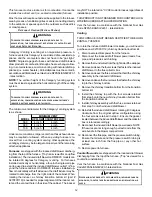
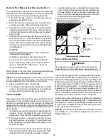
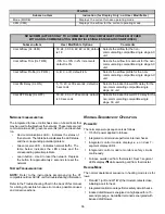
Air cleaner installation 

location 

Maximum 

Heating Airflow 

Filter (Media) 

Dimensions Part 

Number 

Air Cleaner 

Family 

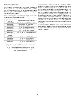
Side or bottom return 

1200 CFM 

16 in X 20 in x 5¼" 

AM11-1620-5 

AM11-5 

Side or bottom return 

1600 CFM 

16 in X 25 in x 5¼" 

AM11-1625-5 

Side or bottom return 

1600 CFM 

20 in X 20 in x 5¼" 

AM11-2020-5 

Side or bottom return 

2000 CFM 

20 in X 25 in x 5¼" 

AM11-2025-5 

Side return 

(for 2 separate returns) 

2 X 1600 CFM 

2, 16 in X 25 in x 5¼" 

AM11-3225-5 

AM11-3225 

Side return (Right angle) 

2000 CFM 

20 in X 25 in x 5¼" 

AM11-2025-5RA 

AM11-5RA 

Bottom return (platform) 

2000 CFM 

20 in X 25 in x 5¼" 

AM11-2832-5PP 

AM11-5PP 

Bottom return (platform) 

2000 CFM 

20 in X 25 in x 5¼" 

AM11-2843-5PP 


AM11-5 

Family 

AM11-5RA 

Family 

AM11-5PP 

Family 


S

TART

-

UP

 P

ROCEDURE

 A

ND

 A

DJUSTMENT

Furnace must have a 115 VAC power supply properly connected
and grounded.  Proper polarity must be maintained for correct
operation.  In addition to the following start-up and adjustment
items, refer to further information in 

Operational Checks 

sec-

tion.

H

EAT

 A

NTICIPATOR

 S

ETTING

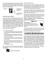
The heat anticipator in older, non-electronic room thermostats
must be correctly adjusted to obtain the proper number of cycles
per hour and to prevent “overshooting” of the setting.  Set the
heat anticipator setting to  0.7 amps.  Follow the thermostat
manufacturer’s instructions on how to adjust the heat anticipa-
tor setting.

F

URNACE

 O

PERATION

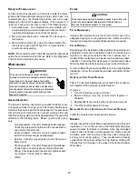
Purge gas lines of air prior to startup.  Be sure not purge lines
into an enclosed burner compartment.

Check for leaks using an approved chloride-free soap and wa-
ter solution, an electronic combustible gas detector, or other
approved method.  Verify that all required kits (propane gas,
high altitude, etc.) have been appropriately installed.

F

URNACE

 S

TARTUP

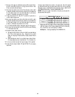
1. Close the manual gas shutoff valve external to the furnace.
2. Turn off the electrical power to the furnace.
3. Set the room thermostat to the lowest possible setting.
4. Remove the burner compartment door.

NOTE:  

This furnace is equipped with an ignition device which

automatically lights the burner.  Do not try to light the burner by
hand.

5. Move the furnace gas valve manual control to the OFF

position.

6. Wait five minutes then smell for gas. Be sure check

near the floor as some types of gas are heavier than air.

7. If you smell gas after five minutes, immediately follow

the instructions in the 

Safety Instructions

 section of this

manual.  If you do not smell gas after five minutes,  move
the furnace gas valve manual control to the ON position.

8. Replace the burner compartment door.

9. Open the manual gas shutoff valve external to the furnace.

10. Turn on the electrical power to the furnace.

Summary of Contents for DM80VC

Page 1: ...ollow them The precautions listed in this Installation Manual are intended as supplemental to existing practices However if there is a direct conflict between existing practices and the content of thi...

Page 2: ...STALLATION 15 FIX 1 LINER TERMINATION 15 FIX 2 CHANGE VENTING ARRANGEMENTS 15 FIX 3 REBUILD THE CROWN 16 FIX 4 RELINING 16 ELECTRICAL CONNECTIONS 16 WIRING HARNESS 17 115 VOLT LINE CONNECTIONS 17 JUNC...

Page 3: ...EQUENCE OF OPERATION 36 POWER UP 36 HEATING MODE 36 COOLING MODE 38 FAN ONLY MODE 38 OPERATIONAL CHECKS 38 SAFETY CIRCUIT DESCRIPTION 38 INTEGRATED CONTROL MODULE 39 PRIMARY LIMIT 39 AUXILIARY LIMIT 3...

Page 4: ...in the LOCATION REQUIREMENTS AND CONSIDERATIONS section of this manual This furnace may be used as a construction site heater only if certain conditions are met These conditions are listed in the PRO...

Page 5: ...ERATURES AND WILL BE VACANT ALL WATER BEARING PIPES SHOULD BE DRAINED THE BUILDING SHOULD BE PROPERLY WINTERIZED AND THE WATER SOURCE CLOSED IN THE EVENT THAT THE BUILDING MAY BE EXPOSED TO FREEZING T...

Page 6: ...RE EXPLOSION SMOKE SOOT CONDENSATION ELECTRICAL SHOCK OR CARBON MONOXIDE MAY RESULT FROM IMPROPER INSTALLATION REPAIR OPERATION OR MAINTENANCE OF THIS PRODUCT WARNING TO PREVENT PERSONAL INJURY OR DEA...

Page 7: ...ollowing final construction clean up by a qualified person ELECTROSTATIC DISCHARGE ESD PRECAUTIONS NOTE Discharge body s static electricity before touching unit An electrostatic discharge can adversel...

Page 8: ...l J Load Cal culations published by the Air Conditioning Contractors of America In the USA this furnace MUST be installed in accordance with the latest edition of theANSI Z223 1 booklet entitled Natio...

Page 9: ...oximately 1 1 2 larger than the base of the furnace Ensure upflow or horizontal furnaces are not installed directly on carpeting or any other combustible material The only combustible material allowed...

Page 10: ...EATER SHOULD TAKE PRECEDENCE OVER MINIMUM FIRE PRO TECTION CLEARANCE Agas fired furnace for installation in a residential garage must be installed so that the ignition source and burners are located n...

Page 11: ...a mise en marche alors que tous les autres appareils raccord s au syst me de ventilation ne sont pas en marche 1 Sceller toutes les ouvertures inutilis es du syst me de ventilation 2 Inspecter le syst...

Page 12: ...e from the right side of the cabinet When rotating the inducer a chimney transition bottom kit part 0270F01119 is needed for proper alignment of the inducer out let and the vent exit hole in the side...

Page 13: ...peratures have a direct impact on the suitability of this type of venting In most situations the existing masonry chimneys will require a properly sized metallic liner POSSIBILITY OF PROPERTY DAMAGE P...

Page 14: ...he lowest existing vent connector and examine the inside of the elbow or tee at the base of the liner Asmall amount of soot may be considered acceptable provided the installer vacuums it away If ruste...

Page 15: ...gh PVC pipe Next use a flashlight and small mirror to sight up the liner B vent must be supported so as to not come into direct contact with the chimney walls or tile liner If it is not it can probabl...

Page 16: ...A B149 2 latest editions and amendments To install the liner read and follow the liner manufacturer s in structions and your local codes Excess liner length should be pulled out of the chimney and cut...

Page 17: ...configured for a right side electrical connection To make electrical connections through the opposite side of the furnace the junction box must be relocated to the left side prior to making electrical...

Page 18: ...olt wiring NOTE For single stage cooling applications a jumper may be located between Y1 and Y2 at the furnace control in order to achieve the desired single stage cooling airflow Use of ramp ing prof...

Page 19: ...HUM TRIM ENABLE Move to the ON position to enable dehumidification ON OFF S5 FOSSIL FUEL APPLICATIONS This furnace can be used in conjunction with a heat pump in a fossil fuel application A fossil fue...

Page 20: ...NEUTRAL HUM OUT HUM IN 24VOLT HUMIDIFIER A 24 volt humidifier can be powered by feeding one of the HUM terminals with a field installed wire from the R terminal or by connecting to the NO side of the...

Page 21: ...This unit is configured for natural gas The appropriate manufacturer s propane gas conversion kit must be applied for propane gas installations If converting to LP gas it is recommended that an LPLP0...

Page 22: ...ough the left side of the furnace the installer must supply the following fittings starting from the gas valve 90 degree elbow Straight pipe to reach the exterior of the furnace A ground joint union d...

Page 23: ...430 830 1 300 2 100 830 1 900 175 170 400 780 1 200 1 900 770 1 700 200 160 380 730 1 100 1 800 720 1 500 Sizing Between First and Second Stage Regulator Maxim um Propane Capacities listed are based o...

Page 24: ...much external static pressure will result in insufficient air that can cause excessive temperature rise This can cause limit switch tripping and heat exchanger failure To determine total external duct...

Page 25: ...used filters may also be centrally located 1 use 2 16X 25filters and two side returns or 20X 25filter on bottomreturn if furnace is connected to a cooling unit over 4tons nominal capacity Consider ins...

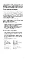
Page 26: ...the setting Set the heat anticipator setting to 0 7 amps Follow the thermostat manufacturer s instructions on how to adjust the heat anticipa tor setting FURNACEOPERATION Purge gas lines of air prior...

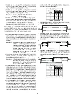
Page 27: ...apacity 4 The display will continue to flash Ft until high capacity 100 is achieved Once achieved the display will show Ft without flashing A 5 minute timer will be started to al low sufficient opport...

Page 28: ...ecessary ad justments to pressure regulator gas piping size etc and or consult with local gas utility 5 Turn OFF gas to furnace at the manual shutoff valve and disconnect manometer Reinstall plug befo...

Page 29: ...PT hose barb fitting from the outlet pressure tap Replace the outlet pressure tap plug and seal with a high quality thread sealer b White Rodgers valve Turn outlet pressure test screw in to seal press...

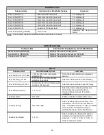
Page 30: ...of seconds per cubic foot sec ft3 of gas being delivered to the furnace If the dial is a two cubic foot dial divide the number of seconds recorded in step 2 by two 4 Calculate the furnace input in BT...

Page 31: ...or other devices may require specific air flows consult installa tion instructions of those devices for requirements 3 Knowing the furnace model locate the high stage cooling air flow charts in the S...

Page 32: ...F DELAY TIMINGS The integrated control module provides a selectable heat off delay function The heat off delay period may be set to 90 120 150 180 seconds using the DIP switches or jumper provided on...

Page 33: ...anual for the airflow delivered during cooling or heat pump heating In continuous fan mode the CTK0 thermostat provides the airflow demand The thermostat may be configured for a low medium or high con...

Page 34: ...le Single Stage AC ComfortNet G W1 W2 Y1 Y2 O 1 2 R C 4 Position Connectors from CTK0 Thermostat Kit System Wiring between Furnace and Non Communicating CompatibleSingleStageAirConditioner NOTE When u...

Page 35: ...heat demand Humidity Fan Speed 1 2 3 4 Select Humidity Fan Speed this option is enabled when Humidity Setting of IND is selected 1 25 2 50 3 75 4 100 of maximum airflow SET UP Submenu Item Indication...

Page 36: ...in 2 increments default is 0 Selects the airflow trim amount for the non communicating compatible single stage AC unit Cool Airflow Profile CL PRFL A B C or D default is A Selects the airflow profile...

Page 37: ...nications Failure 2 Flashes Out of box reset Green Receive LED Off Nopower Communications error 1 Steady Flash No network found Rapid Flashing Normal network traffc On Solid Data 1 Data 2 miss wire Po...

Page 38: ...thermostat contacts open completing the call for cool Outdoor fan and compressor are de energized Circulator blower continues running during a cool off delay period The OFF delay time and airflow leve...

Page 39: ...cable to both installed and uninstalled ungrounded furnaces 1 Disconnect all power to the furnace Do not touch the integrated control module or any wire connected to the control prior to discharging y...

Page 40: ...r flame and flame signal Drainage system Check for blockage and or leakage Check hose connections at and internal to furnace Wiring Check electrical connections for tightness and or corrosion Check wi...

Page 41: ...hanger flue passageways should be inspected at the beginning of each heating season BEFORE LEAVING AN INSTALLATION Cycle the furnace with the thermostat at least three times Verify cooling and fan onl...

Page 42: ...for Service icon illuminated ComfortNet thermostat scrolls Check Furnace message E0 Furnace lockout due to an excessive number of ignition retries 3 total LOCKOUT E0 Failure to establish flame Cause m...

Page 43: ...and ductwork for blockage Clean or remove filters obstruction Check circulator blower speed and performance Correct speed or replace blower motor if necessary Check burners for proper alignment Check...

Page 44: ...d improperly Blocked fue and or inlet air pipe blocked drain system or weak induced draft blower Incorrect pressure switch set point or malfunctioning switch contacts Loose or improperly connected wir...

Page 45: ...ntrol module has lost communications with circulator blower motor MOTOR COMM b1 Loose wiring connection at circulator motor control leads Failed circulator blower motor Failed integrated control modul...

Page 46: ...t scrolls Check Furnace message b7 MOTOR PARAMS b7 Furnace operates at reduced performance or Integrated control module LED display provides b9 error code b9 LOW ID AIRFLOW B9 Blocked filters Restrict...

Page 47: ...D 115 VAC POLARITY DATANOT YET ON NETWORK INVALID MEMORYCARD DATA BLOWER MOTOR NOT RUNNING BLOWER COMMUNICATION ERROR BLOWER HP MIS MATCH BLOWER MOTOR OPERATING IN POWER TEMPERATURE OR SPEED LIMIT BLO...

Page 48: ...ff Delay Short Run 30s ec 50 DC80VC0805C DM 80VC0803B DM 80VC0804C DM 80VC0805C Speed Selection Dip Switches C o o l Selec tio n Switc hes A djus t Selec tio n Switches P ro file Selec tio n Switc hes...

Page 49: ...dd 5 Off Off Minus 5 On Off Add 10 Off On Minus 10 On On A Off Off B On Off C Off On D On On A Off Off B On Off C Off On D On On Disabled Off Enabled On Disabled Off Enabled On 25 Off Off 50 On Off 75...

Page 50: ...1800 C D 60 sec 100 7 5 min 82 60 sec 100 To Set Airflow 1 Select model and desired High Stage CoolingAirflow Determine the corresponding tap A B C or D Set dip switches S3 1 and S3 2 to the appropria...

Page 51: ...51 THIS PAGE LEFT INTENTIONALLY BLANK...

Page 52: ...warranty protection except that failure by California and Quebec residents to register their product does not diminish their warranty rights For Product Registration please register by following this...

Reviews: