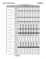
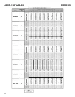
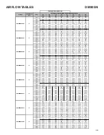
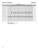
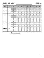
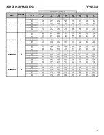
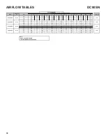
background image

AIRFLOW TABLES

33

0.1

0.2

0.3

0.4

0.5

0.6

0.7

0.8

CFM

CFM

CFM

CFM

CFM

CFM

CFM

CFM

F01

658

585

545

495

444

390

332

151

F02

749

697

652

607

554

509

459

406

F03

925

881

840

800

760

721

681

645

F04

882

841

800

760

719

678

641

602

F05

1330

1295

1273

1251

1223

1195

1168

1142

F06

1130

1090

1059

1022

991

957

926

895

F07

1158

1113

1090

1057

1024

996

964

935

F08

1270

1235

1208

1179

1147

1119

1088

1060

F09

1417

1380

1359

1336

1314

1288

1261

1238

F01

659

599

542

490

437

383

320

N/A

F02

1268

1221

1188

1154

1122

1091

1060

1029

F03

1087

1044

1008

973

938

905

871

841

F04

1118

1070

1033

997

963

929

896

865

F05

1308

1262

1224

1197

1167

1141

1117

1089

F06

868

823

780

741

699

662

624

584

F07

922

877

835

795

757

718

679

642

F08

1382

1341

1311

1291

1263

1234

1206

1177

F09

1492

1448

1409

1381

1354

1332

1310

1288

F01

764

695

630

559

485

415

358

N/A

F02

1287

1235

1191

1147

1104

1062

1020

979

F03

1339

1301

1258

1217

1174

1131

1090

1048

F04

1396

1346

1298

1257

1217

1175

1135

1098

F05

1185

1135

1088

1040

992

947

901

855

F06

1500

1460

1420

1360

1340

1294

1256

1219

F07

1591

1539

1493

1454

1416

1379

1347

1311

F08

1675

1622

1583

1545

1510

1474

1440

1402

F09

1790

1741

1701

1668

1631

1599

1567

1532

F01

710

646

580

515

432

367

314

274

F02

1298

1255

1216

1178

1140

1102

1067

1028

F03

1209

1166

1124

1083

1045

1005

964

923

F04

1138

1091

1045

1001

959

920

876

832

F05

1391

1352

1314

1278

1241

1209

1175

1140

F06

977

931

880

836

785

734

683

626

F07

1036

985

940

895

848

799

751

705

F08

1456

1414

1376

1341

1302

1270

1238

1200

F09

1533

1488

1452

1415

1383

1350

1317

1286

F01

841

657

595

522

439

367

315

N/A

F02

1141

1089

1045

1001

958

914

869

823

F03

1311

1267

1226

1189

1150

1114

1072

1034

F04

1395

1347

1309

1270

1233

1199

1164

1125

F05

1490

1447

1407

1373

1336

1303

1269

1237

F06

1553

1510

1469

1435

1401

1368

1335

1300

F07

1593

1548

1508

1474

1440

1409

1376

1343

F08

1776

1735

1695

1661

1628

1601

1570

1542

F09

1853

1812

1773

1739

1708

1679

1650

1623

F01

837

752

671

576

501

426

361

315

F02

1316

1270

1218

1166

1114

1061

1000

962

F03

1353

1323

1286

1235

1183

1131

1085

1040

F04

1587

1544

1506

1459

1416

1372

1323

1281

F05

1731

1673

1632

1587

1546

1506

1463

1421

F06

1794

1744

1709

1671

1632

1591

1555

1513

F07

1861

1805

1761

1720

1681

1642

1603

1565

F08

1910

1873

1839

1798

1761

1723

1686

1648

F09

2110

2055

2035

2003

1973

1946

1907

1890

F01

802

724

637

551

468

389

342

294

F02

1405

1356

1308

1262

1210

1182

1155

1102

F03

1574

1531

1484

1440

1392

1357

1306

1256

F04

1619

1575

1526

1489

1446

1404

1355

1313

F05

1688

1641

1600

1557

1513

1477

1428

1381

F06

1811

1769

1730

1686

1649

1610

1572

1525

F07

1857

1812

1774

1733

1697

1662

1622

1586

F08

1892

1850

1805

1774

1735

1692

1658

1621

F09

2116

2073

2039

2005

1981

1945

1909

1879

F01

851

774

692

615

535

470

411

359

F02

1677

1629

1583

1540

1498

1449

1399

1349

F03

1537

1489

1444

1404

1365

1322

1272

1211

F04

1416

1365

1315

1267

1220

1163

1106

1048

F05

1154

1098

1043

983

932

874

819

755

F06

1806

1764

1729

1688

1654

1615

1578

1535

F07

1869

1816

1773

1731

1693

1661

1629

1589

F08

1947

1903

1865

1833

1802

1769

1743

1708

F09

2107

2066

2030

1996

1963

1932

1899

1867

DM80SN0805C*

G

DM80SN1005C*

G

DM80SN0803B*

G

DM80SN0804B*

G

DM80SN1205D*

G

CIRCULATION AIRFLOW

MODEL

THERMOSTAT 

CALL

TAP #

EXTERNAL STATIC PRESSURE, (INCHES WATER COLUMN)

G

G

G

DM80SN0403A*

DM80SN0603A*

DM80SN0604B*

DM80SN

Summary of Contents for DM80SN

Page 1: ...anual only licensed personnel should service the equipment Improper installation adjustment servicing or repair of the equipment specified in this manual or attempting to install adjust service or rep...

Page 2: ...EVIEW ALL SERVICE INFORMATION IN THE APPROPRIATE SERVICE MANUAL BEFORE BEGINNING REPAIRS IMPORTANT NOTICES RECOGNIZE SAFETY SYMBOLS WORDS AND LABELS WARNING This unit should not be connected to or use...

Page 3: ...Installation and service must be performed by a qualified installer service agency or the gas supplier IMPORTANT INFORMATION WARNING Should overheating occur or the gas supply fail to shut off turn of...

Page 4: ...rcular a trav s del aparato cuando se opera en cualquier modo B10259 216 CO can cause serious illness including permanent brain damage or death B10259 216 RISQUE D EMPOISONNEMENT AU MONOXYDE DE CARBON...

Page 5: ...itial Release B 1st Revision Configuration M Upflow Horizontal Major Revision C Downflow Horizontal A Initial Release B 1st Revision Nox AFUE 80 80 AFUE 92 92 AFUE 96 96 AFUE 97 97 AFUE Cabinet Width...

Page 6: ...cause death or serious illness and which are known to the state of California to cause cancer birth defects or other reproductive harm This product contains fiberglass insulation Fiberglass insulatio...

Page 7: ...grounded object Product Application This product is designed for use as a residential home gas furnace It is not designed or certified for use in mobile home trailer or recreational vehicle applicatio...

Page 8: ...ating Inlet gas supply pressures must be maintained within the ranges specified below The supply pressure must be con stant and available with all other household gas fired appli ances operating The m...

Page 9: ...ted beside the low voltage thermostat connection strip Twinning allows simultaneous operation of two furnaces and forces the indoor blower motors of each furnace to oper ate synchronously into a commo...

Page 10: ...is is a 24 volt circuit only the common con nection must be on C terminal of the low voltage terminal strip where thermostat wires are con nected Wiring for this circuit must NOT be con nected to the...

Page 11: ...s the available speeds for Low High heat mode 3 When the center switch is pressed the current displayed speed shall be selected and control shall apply the newly selected speed in next heating call NO...

Page 12: ...rtment door and move the furnace gas valve manual control to the OFF position 3 Close the manual gas shutoff valve external to the furnace 4 Replace the burner compartment door Filters Filters must be...

Page 13: ...e then should be wired to the furnace accordingly CHECKING FOR PHASING PRIMARY TO SECONDARY OF UNMARKED TRANSFORMERS VOLT OHM METER G ND PRIMARY SECONDARY TRANSFORMER R C METER READS 24 VOLTS LINE VOL...

Page 14: ...ormance Filters should be cleaned permanent or replaced disposable every two months or as required It is the owner s responsibility to keep air filters clean When replacing a filter it must be replace...

Page 15: ...the unit adjust the gas valve pressure regulator or resize orifices CAUTION Always connect a manometer to the outlet tap at the gas valve before adjusting the pressure regulator In no case should the...

Page 16: ...79 947 45 20 40 80 160 400 20 45 90 180 360 900 46 78 157 391 21 43 86 171 343 857 47 19 38 76 153 383 22 41 82 164 327 818 48 75 150 375 23 39 78 157 313 783 49 147 367 24 37 75 150 300 750 50 18 36...

Page 17: ...CHECKING AUXILIARY LIMIT CONTROL 22 S 302 CHECKING FLAME ROLLOUT CONTROL 22 S 303 INDUCED DRAFT BLOWER MOTOR 23 S 304 CHECKING GAS VALVE REDUNDANT 23 S 305 CHECKING MAIN BURNERS 24 S 306 CHECKING ORI...

Page 18: ...ced replace with AWM 105 C 2 64 thick insulation of the same gauge or its equivalent CHECKING THERMOSTAT WIRING AND ANTICIPATOR S 3A THERMOSTAT AND WIRING WARNING Disconnect ALL power before servicing...

Page 19: ...r completing check and or replacement of trans former and check and or repair of control circuit reinstall blower compartment door 8 Turn on electrical power and verify proper unit operation S 16 CHEC...

Page 20: ...es for the quantity of air If the total external static pressure exceeds the minimum or maximum allowable statics check for closed dampers reg isters undersized and or oversized poorly laid out duct w...

Page 21: ...0 CHECKING PRIMARY LIMIT CONTROL All use a nonadjustable automatic reset bi metal type limit control Refer to the following drawing for the location of the primary limit Location of Primary Limit Prim...

Page 22: ...sonal injury or death VOLT OHM METER RED RESET BUTTON COLOR IDENTIFYING TAB Testing Auxiliary Limit Control WARNING To avoid possible fire only reset the auxiliary limit control once If it should open...

Page 23: ...regulation and 100 percent safety shut off WARNING Disconnect ALL power before servicing Single stage gas valves should be tested on the furnace with 24 VAC connected to the gas valve and manometers r...

Page 24: ...er to prevent distortion In no instance should an orifice be peened over and redrilled This will change the angle or deflection of the vacuum effect or entraining of primary air which will make it dif...

Page 25: ...er before servicing or in stalling this unit Multiple power sources may be present Failure to do so may cause proper ty damage personal injury or death 5 Disconnect manometer after turning off gas at...

Page 26: ...ve the outlet pressure boss plug Install an 1 8 NPT hose barb fitting into the outlet pressure tap b Attach a hose and manometer to the outlet pres sure barb fitting c Turn ON the gas supply d Turn on...

Page 27: ...rature the igniter ohm reading should be from 37 68 ohms S 309 CHECKING FOR FLASHBACK Flashback will also cause burning in the burner venturi but is caused by the burning speed being greater than the...

Page 28: ...SI Z223 1 and information provided by the gas supplier to determine the proper orifice size S 312 CHECKING FOR DELAYED IGNITION Delayed ignition is a delay in lighting a combustible mixture of gas and...

Page 29: ...out The following drawings illustrate from a bottom view the ap proximate distances for the ignitor and flame sensor to the gas in shot burner You will note they are in the main burner stream not in t...

Page 30: ...80SN0803B 0 70 0 06 0 85 0130F00505 DM80SN0804B 0 70 0 06 0 85 0130F00505 DM80SN0805C 0 75 0 07 0 90 0130F00506 DM80SN1005C 0 70 0 06 0 85 0130F00505 DM80SN1205D 0 80 0 05 0 95 0130F00507 DC80SN0403A...

Page 31: ...67 315 N A F02 1141 1089 1045 1001 958 914 869 823 F03 1311 1267 1226 1189 1150 1114 1072 1034 F04 1395 1347 1309 1270 1233 1199 1164 1125 F05 1490 1447 1407 1373 1336 1303 1269 1237 F06 1553 1510 146...

Page 32: ...22 439 367 315 N A F02 1141 1089 1045 1001 958 914 869 823 F03 1311 1267 1226 1189 1150 1114 1072 1034 F04 1395 1347 1309 1270 1233 1199 1164 1125 F05 1490 1447 1407 1373 1336 1303 1269 1237 F06 1553...

Page 33: ...F01 841 657 595 522 439 367 315 N A F02 1141 1089 1045 1001 958 914 869 823 F03 1311 1267 1226 1189 1150 1114 1072 1034 F04 1395 1347 1309 1270 1233 1199 1164 1125 F05 1490 1447 1407 1373 1336 1303 12...

Page 34: ...2 1141 52 1089 54 1045 57 1001 59 958 62 914 869 823 F03 1311 45 1267 47 1226 48 1189 50 1150 52 1114 1072 1034 F04 1395 42 1347 44 1309 45 1270 47 1233 48 1199 1164 1125 F01 837 N A 752 N A 671 N A 5...

Page 35: ...62 1233 1207 F01 760 697 636 569 481 402 349 300 F02 1286 1238 1196 1157 1117 1077 1036 998 F03 1393 1348 1308 1270 1230 1196 1158 1123 F04 1459 1414 1371 1336 1297 1264 1229 1193 F05 1753 1713 1677 1...

Page 36: ...1262 1233 1207 F01 760 697 636 569 481 402 349 300 F02 1286 1238 1196 1157 1117 1077 1036 998 F03 1393 1348 1308 1270 1230 1196 1158 1123 F04 1459 1414 1371 1336 1297 1264 1229 1193 F05 1753 1713 167...

Page 37: ...1348 1318 1289 1262 1233 1207 F01 760 697 636 569 481 402 349 300 F02 1286 1238 1196 1157 1117 1077 1036 998 F03 1393 1348 1308 1270 1230 1196 1158 1123 F04 1459 1414 1371 1336 1297 1264 1229 1193 F0...

Page 38: ...A 697 N A 636 N A 569 N A 481 N A 402 349 300 F02 1286 46 1238 48 1196 50 1157 51 1117 53 1077 1036 998 F03 1393 43 1348 44 1308 45 1270 47 1230 48 1196 1158 1123 F04 1459 41 1414 42 1371 43 1336 44 1...

Page 39: ...set at 7 Secs Adjustments can be made in 7 Secs increments from0 to 35 Secs Cool Off Delay Delay Seconds Default set at 65 Secs Adjustments can be made in 5 Secs increments from 0 to 120 Secs Blower...

Page 40: ...1 STAGE STATUS CODES 40 Idle Continous Fan F Compressor Cooling Low Stage Compressor Cooling High Stage Gas heat Single Stage Control OEM test Mode Mode Main Menu STATUS MENU...

Page 41: ...ulator blower motor Correct speed or replace blower motor if necessary Loose or improperly connected wiring in high limit circuit Tighten or correct wiring connection Flame sensed with no call for hea...

Page 42: ...ontrol module Blown fuse or tripped circuit breaker Correct condition which caused fuse to open replace fuse Integrated control module is non functional Replace non functional integrated control modul...

Page 43: ...PERATURE RATING OF AT LEAST 105v C USE COPPER CONDUCTORS ONLY 4 UNIT MUST BE PERMANENTLY GROUNDED AND CONFORM TO N E C AND LOCAL CODES 5 TO RECALL THE LAST 6 FAULTS MOST RECENT TO LEAST RECENT DEPRESS...

Page 44: ...is very interested in all product comments Please fill out the feedback form on the following link https daikincomfort com contact us You can also scan the QR code on the right to be directed to the f...

Reviews: