


PRODUCT DESIGN
30
Humidifier Wiring
There are several options for connecting humidifier wiring to
the current communicating furnace control board
(PCBKF103, PCBK104, and PCBKF105)
Single HUM terminal
The single HUM terminal is energized
with 115 volts whenever the draft inducer is running. This
function is present regardless of thermostat type. This ter-
minal may be used to power a humidifier transformer. A
field supplied humidistat must be provided with this option.
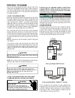
HUM IN – HUM OUT Terminals
Present on communicating
furnace models built with a (PCBKF103,PCBK104, and
PCBKF105) board. These terminals may be used when a
CTK02** or CTK03AB communicating thermostat is used.
These thermostats are capable of initiating a call for
humidity.The HUM IN – HUM OUT terminals are not ener-
gized by factory wiring and must be field wired.Typical wir-
ing would be to supply the HUM IN contact with 115 volts
from the furnace L1 terminal and connect a line voltage hu-
midifier / transformer between HUM OUT and the control
board neutral.
Options for control:
With the CTK02 thermostat. From the Main Menu > Clock
& Display > Hum Display > (On). Enter the Advanced menu
by pressing left and right arrows for three seconds > Com
Devices > Furnace > Setup > Humidity > (On or Indepen-
dent) If “On” is selected, the HUM IN – HUM OUT contacts
will close during a call for heat if the room humidty is below
the humidity set point selected on the CTK02**. The control
board also runs the furnace blower on constant fan speed
to support the call for humidification. If “IND” is selected,
the HUM IN – HUM OUT contacts will close with or without
a call for heat if the room humidity is below the humidity
setpoint selected on the CTK02**. The control board also
runs the furnace blower on constant fan speed to support
the call for humidification.
With the CTK03AB & CTK04AA thermostat. From the Main
Menu > Installer Options (enter 4 digit passcode from the
Dealer Information Menu) > View / Edit Current Setup >
Humidification > Humidifier Type (Steam or Bypass / fan
powered) > Modes Allowing Humidification (Heat, Off) > Hu-
midification Control > (Humidify only when fan is on, Hu-
midify on demand – thermostat controls fan, Humidify on
demand – equipment controls fan)
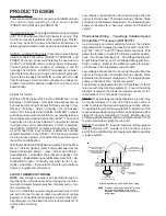
24 VOLT THERMOSTAT WIRING
NOTE:
Low voltage connections can be made through ei-
ther the right or left side panel. Wire routing must not inter-
fere with circulator blower operation, filter removal, or rou-
tine maintenance.
A 40 V.A. transformer and an integrated electronic control
are built into the furnace to allow use with most cooling
equipment. Consult the wiring diagram, located in the Tech-
nical Manual or on the blower door for further details of 115
Volt and 24 Volt wiring.
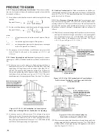
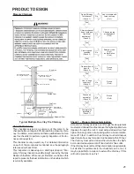
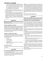
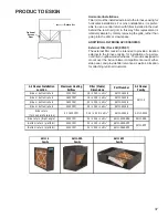
Low voltage connections can be made through either the
right or left side panel. Thermostat wiring entrance holes
are located in the blower compartment. The following figure
shows connections for a “heat only” system and “heat/cool
system”.
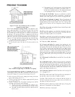
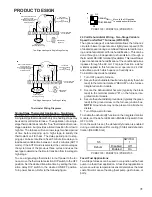
Thermostat Wiring - Two-Stage Variable Speed
ComfortNet™ Furnaces (WR 50C51)
As a two-stage non-communicating furnace, the furnace
integrated control module provides terminals for both “W1”
and “W2”, and “Y1” and “Y2” thermostat connections. This
allows the furnace to support the following system applica-
tions: ‘Two-Stage Heating Only’, ‘Two-Stage Heating with
Single Stage Cooling’, and ‘Two-Stage Heating with Two-
Stage Cooling’. Refer to the following figures for proper
connections to the integrated control module.
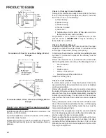
Low voltage connections can be made through either the
right or left side panel. Thermostat wiring entrance holes
are located in the blower compartment. The following figure
shows connections for a “heat/cool system”.
This furnace is equipped with a 40 VA transformer to facili-
tate use with most cooling equipment. Consult the wiring
diagram, located on the blower compartment door, for fur-
ther details of 115 Volt and 24 Volt wiring.
NOTE:
For single stage cooling applications, a jumper may
be required between Y1 and Y2 at the furnace control in
order to achieve the desired single stage cooling airflow.
Consult the blower performance tables to determine if the
required single stage cooling airflow can be delivered at low
stage (Y1 input) or high stage (Y2 input). Additionally, use
of ramping profile features require a jumper between Y1 and
O when used with a straight cooling unit.
NOTE:
Thermostat “R” required if outdoor unit is equipped
with a Comfort Alert™ module or if the out door unit is a
part of the ComfortNet family of equipment AND is wired as
a legacy system.
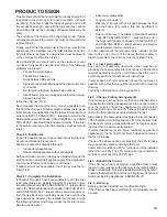
Y
R
R
Y
C
NEU
Furnace Integrated
Control Module
Remote
Condensing Unit
(Single-Stage Cooling)
Dehumidistat
[Optional]
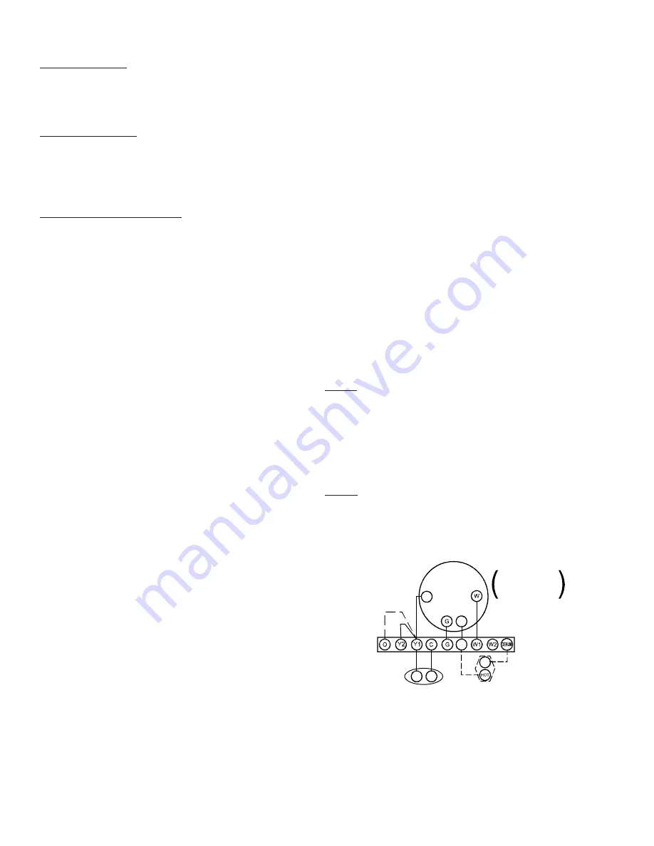
To apply a single-stage Heating Thermostat,
the thermostat selector switch on the
Integrated Control Module
be set on
single-stage.
must
NOTE:
Single Stage Heating with Single Stage Cooling
Thermostat
Single Stage Heating with
Single Stage Cooling
Place Jumper Between Y1
and O For Proper
Dehumidification Operation
and Proper Ramping
Profile Operation