


PRODUCT DESIGN
20
9.3.8.4
Ducts shall not serve both upper and lower combustion air
openings where both such openings are used. The separation between
ducts servicing upper and lower combustion air openings shall be main-
tained to the source of combustion air.
9.3.8.5
Ducts shall not be screened where terminating in an attic space.
9.3.8.6
Horizontal upper combustion air ducts shall not slope down-
ward toward the source of combustion air.
9.3.8.7
The remaining space surrounding a chimney liner, gas vent, spe-
cial gas vent, or plastic piping installed within a masonry, metal, or
factory built chimney shall not be used to supply combustion air.
Exception: Direct vent appliances designed for installation in a solid
fuel-burning fireplace where installed in accordance with the
manufacture’s installation instructions.
9.3.8.8
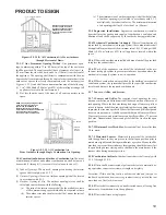
Combustion air intake openings located on the exterior of the
building shall have the lowest side of the combustion air intake openings
located at least 12 in. (300 mm) vertically from the adjoining grade level.
Category I Venting (Vertical Venting)
(80% Furnaces Only)
WARNING
T
O PREVENT POSSIBLE PERSONAL INJURY OR DEATH DUE TO
ASPHYXIATION, NON-CONDENSING GAS FIRED WARM AIR FURNACES MUST
BE
C
ATEGORY
I
VENTED.
D
O NOT VENT ANY OF THESE FURNACES USING
C
ATEGORY
III
VENTING.
Category I Venting is venting at a non-positive pressure. A
furnace vented as Category I is considered a fan-assisted
appliance and does not have to be "gas tight."
NOTE:
Single-
Stage and Two-Stage gas furnaces with induced draft blow-
ers draw products of combustion through a heat exchanger
allowing in some instances common venting with natural
draft appliances (i.e. water heaters).
All installations must be vented in accordance with National
Fuel Gas Code NFPA 54/ANSI Z223.1 - latest edition. In
Canada, the furnaces must be vented in accordance with
the National Standard of Canada, CAN/CGA B149.1 and
CAN/CGA B149.2 - latest editions and amendments.
NOTE:
The vertical height of the Category I venting system
must be at least as great as the horizontal length of the
venting system.
WARNING
T
O PREVENT POSSIBLE DEATH OR PERSONAL INJURY DUE TO
ASPHYXIATION, COMMON VENTING WITH OTHER MANUFACTURER'S
INDUCED DRAFT APPLIANCES IS NOT ALLOWED.
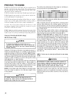
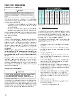
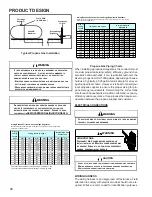
The minimum vent diameter for the Category I venting sys-
tem is as shown in the following chart:
UPFLOW
COUNTERFLOW
060
4 Inch
4 Inch
080
4 Inch
4 Inch
100
5 Inch
5 Inch
MINIMUM VENT
MODEL
Under some conditions, larger vents than those shown above
may be required or allowed.
When an existing furnace is removed from a venting system
serving other appliances
, the venting system may be too
large to properly vent the remaining attached appliances.
For complete details refer to
Exisiting Furnace Removal
sec-
tion of this manual.
When resizing any portion of the common venting system,
use the appropriate table in Appendix G in the latest edition
of the National Fuel Gas Code NFPA 54/ANSI Z223.1.
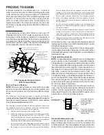
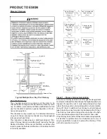
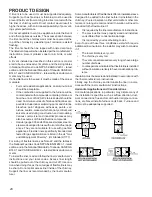
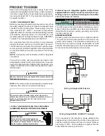
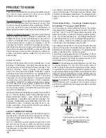
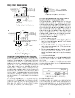
Upflow or Horizontal units
are shipped with the induced
draft blower discharging from the top of the furnace ("Top" is
as viewed for an upflow installation). The induced draft blower
can be rotated 90 degrees for Category I venting. Refer to
the following figure. For horizontal installations, a four inch
single wall pipe can be used to extend the induced draft
blower outlet 1/2” beyond the furnace cabinet. Vent the fur-
nace in
accordance with the National Fuel Gas Code NFPA
54/ANSI Z223.1 - latest edition. In Canada, vent the furnace
in accordance with the National Standard of Canada, CAN/
CGA B149.1 and CAN/CGA B149.2 - latest editions and
amendments.
NOTE:
This furnace is not design certified to be horizontally
vented.
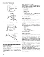
WARNING
T
O PREVENT DEATH OR SERIOUS ILLNESS TO BUILDING OCCUPANTS DUE
TO FLUE PRODUCTS LEAKING INTO THE BUILDING, PROPER INSTALLATION OF
GASKETS AND SCREWS IS ESSENTIAL FOR PROVIDING A GAS TIGHT SEAL
BETWEEN THE PARTITION PANEL AND THE INDUCED DRAFT BLOWER.
Make sure all wires are at least one inch from flue pipe.
Relocate junction box to right side of cabinet if necessary.
Refer to
Electrical Connections
section of this manual for
instructions.