


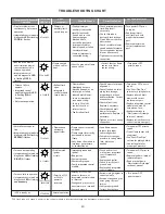
25
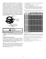
Wiring Harness
The wiring harness is an integral part of this furnace. Wires
are color coded for identification purposes. Refer to the
wiring diagram for wire routings. If any of the original
wire as supplied
with the furnace must be replaced, it must
be replaced with wiring material having a temperature rating
of at least 105° C. Any replacement wiring must be a copper
conductor.
115 Volt Line Connections
Before proceeding with electrical connections, ensure that
the supply voltage, frequency, and phase correspond to
that specified on the unit rating plate. Power supply to the
furnace must be NEC Class 1, and must comply with all
applicable codes. The furnace must be electrically grounded
in accordance with local codes or, in their absence, with the
latest edition of The National Electric Code, ANSI NFPA 70
and/or The Canadian Electric Code CSA C22.1.
Use a separate fused branch electrical circuit containing
properly sized wire, and fuse or circuit breaker. The fuse
or circuit breaker must be sized in accordance with the
maximum overcurrent protection specified on the unit rating
plate. An electrical disconnect must be provided at the
furnace location.
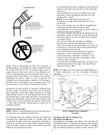
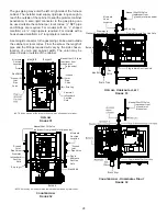
Connect hot, neutral, and ground wires as shown in the
wiring diagram located on the unit’s blower door. For direct
vent applications, the cabinet opening to the junction box
must be sealed air tight using either an UL approved bushing
such as Heyco Liquid Tight or by applying non-reactive UL
approved sealant to bushing.
Line polarity must be observed when making field connections.
Line voltage connections can be made through either the
right or left side panel. The furnace is shipped configured for
a right side (left side for counterflows) electrical connection
with the junction box located inside the burner compartment.
To make electrical connections through the opposite side of
the furnace, the junction box must be relocated to the other
side of the burner compartment prior to making electrical
connections. To relocate the junction box, follow the steps
shown below.
NOTE:
Wire routing must not to interfere with circulator
blower operation, filter removal, or routine maintenance.
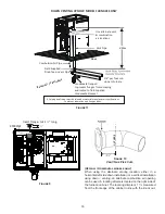
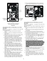
Junction Box Relocation
WARNING
HIGH VOLTAGE
To avoid personal injury or death due to
electrical shock, disconnect electrical power
before servicing or changing any electrical
wiring.
CAUTION
To prevent unreliable operation or equipment damage, the
gas manifold pressure must be as specified on the unit rating
plate. Only minor adjustments should be made by adjusting
the gas valve pressure regulator.
WARNING
HIGH VOLTAGE
To avoid risk of electrical shock, wiring to
the unit must be polarized and grounded.
CAUTION
Label all wires prior to disconnection when servicing
controls. Wiring errors can cause improper and dangerous
operation after servicing.
Line voltage connections can be made through either the
right or left side panel. The furnace is shipped configured
for a left side electrical connection. To make electrical
connections through the opposite side of the furnace, the
junction box must be relocated to the right side prior to
making electrical connections. To relocate the junction box,
perform the following steps.
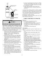
1. Remove the burner compartment door.
2. Remove and save the two screws securing the
junction box to the side panel.
3. Relocate junction box and associated plugs and
grommets to opposite side panel. Secure with screws
removed in step 2.
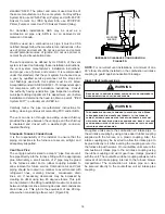
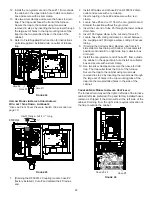
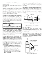
To ensure proper unit grounding, the ground wire should run
from the furnace ground screw located inside the furnace
junction box all the way back to the electrical panel.
NOTE:
Do not use gas piping as an electrical ground. To confirm
proper unit grounding, turn off the electrical power and
perform the following check.
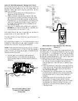
1. Measure resistance between the neutral (white)
connection and one of the burners.
2. Resistance should measure 10 ohms or less.
This furnace is equipped with a blower door interlock switch
which interrupts unit voltage when the blower door is opened
for servicing. Do not defeat this switch.
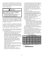
24 Volt Thermostat Wiring
Low voltage connections can be made through either the
right or left side panel. Thermostat wiring entrance holes
are located in the blower compartment. The following figure
shows connections for a “heat/cool system”.


