


19
Vent/Flue and Combustion Air Pipe Terminations
The vent/flue and combustion air pipes may terminate
vertically, as through a roof, or horizontally, as through an
outside wall.
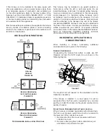
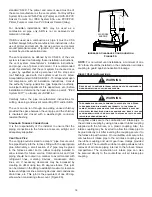
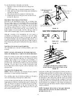
Vertical pipe terminations should be as shown in the
following figure. Refer to
Vent/Flue Pipe and Combustion
Pipe - Termination Locations
for details concerning location
restrictions. The penetrations through the roof must be
sealed tight with proper flashing such as is used with a
plastic plumbing vent.
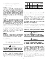
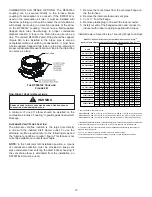
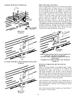
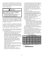
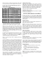
Vent & Combustion Air Intake Measurements for
Standard Horizontal Terminations (Dual Pipe)
Center to center = 10” min / 24” max.
Vertical separation: 0” - 24”
Vent termination from wall = 8” min / 12” max.
Combustion air intake from wall = 6” max.
Vent and intake clearance to ground or anticipated snow
level = 12” min.
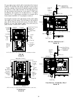
Vent/Intake Terminations For Installation of
Multiple Direct Vent Furnaces
If more than one direct vent furnace is to be installed
vertically through a common roof top, maintain the same
minimum clearances between the exhaust vent and air
intake terminations of adjacent units as with the exhaust
vent and air intake terminations of a single unit.
If more than one direct vent furnace is to be installed
horizontally through a common side wall, maintain the
clearances as in the following figure. Always terminate
all exhaust vent outlets at the same elevation and always
terminate all air intakes at the same elevation.
Concentric Vent Termination
Refer to the directions provided with the Concentric Vent Kit
(DCVK) for installation specifications.
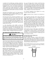
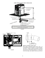
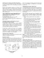
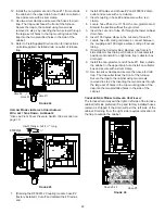
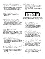
Side Wall Vent Kit
This kit is to be used with 2” or 3” direct vent systems. The
vent kit must terminate outside the structure and may be
installed with the intake and exhaust pipes located side-
by-side or with one pipe above the other. These kits are
NOT
intended for use with single pipe (non-direct vent)
installations.
Ve rtica l Installation
H orizontal Installation
Side Wall Vent Kit
Figure 19
Refer to the directions furnished with the Side Wall Vent
Kit (p/n 0170K00000S or 0170K00001S) for installation
specifications.
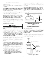
Condensate Drain Lines & Drain Trap
A condensing gas furnace achieves its high level of efficiency
by extracting heat from the products of combustion to the
point where condensation takes place. The condensate
must be collected in the furnace drain trap and routed to
an appropriate drain location in compliance with local and
national codes.
Follow the bullets listed below when installing the drain
system. Refer to the following sections for specific details
concerning furnace drain trap installation and drain hose
hook ups.
•
The drain trap supplied with the furnace must be
used.
•
The drain trap must be primed at time of installation.
•
The drain line between furnace and drain location
must meet local and nation codes.
•
The drain line between furnace and drain location
must maintain a ¼ inch per foot downward slope
toward the drain.
• Do not trap the drain line in any other location than at
the drain trap supplied with the furnace.
•
If the drain line is routed through an area which may
see temperatures near or below freezing, precautions
must be taken to prevent condensate from freezing
within the drain line.
•
If an air conditioning coil is installed with the furnace,
a common drain may be used. An open tee must be
installed in the drain line, near the cooling coil, to
relieve positive air pressure from the coil’s plenum.
This is necessary to prohibit any interference with the
function of the furnace’s drain trap.
NOTE:
In vertical installations, air conditioning coil
condensate may drain into the furnace trap as long as there
is a trap between the coil and the furnace trap and the drain
pipe is not terminating below the water level of the furnace
trap.
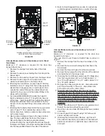
General Drain Information
All furnace models come with a factory installed drain trap.
For vertical installations, the trap will remain in the factory
position except for a counterflow when the installer desires
the drain to exit the right side. All furnace models installed
horizontally require the trap to be relocated. Many drain
hoses have a built–in grommet which will provide a cabinet
seal when installed. See instructions below for your model
and installation position.
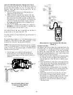
NOTE:
Both sides of the drain trap
must be primed prior to initial furnace start up.


