4
Pre-Installation Instructions
Carefully read all instructions for the installation prior to
installing product. Make sure each step or procedure is
understood and any special considerations are taken into
account before starting installation. Assemble all tools,
hardware and supplies needed to complete the installation.
Some items may need to be purchased locally. Make sure
everything needed to install the product is on hand before
starting.
Location
NOTE: Airhandlers are designed for indoor
installation only.
When installing this airhandler in an enclosed area, such
as a garage/parking area, as with any carbon monoxide
producing device (i.e. and automobile, space heater, water
heater, etc.), insure that the area is properly ventilated.
The DAX airhandler is suitable for installation in multiple
locations including:
•
Overhead (attic/mezzanine, etc.)
• Closet/mechanical room
When installing this airhandler, consideration is to be given
to minimize the length of refrigerant tubing. Also, do not
install the airhandler in a location either above or below the
condenser that violates the instructions provided with the
condenser.
The clearance from a combustible surface to the unit may
be 0”. However, service clearance is to take precedence.
In addition allow a minimum of 36” in front of the unit for
service clearance. Allow sufficient clearance to remove
the heater elements for service or replacement in heat kits
when utilized in application.
When installing in an area directly over a finished ceiling
(such as an attic), an emergency drain pan is required
directly under the unit. See local and state codes for
additional requirements.
When installing this unit in an area that may become wet,
elevate the unit with a sturdy, non-porous material.
In installations that may lead to physical damage
(warehouse, industrial sites, etc.), it is advised to install a
protective barrier to prevent such damage.
Ductwork
This DAX air handler is designed for a complete supply
and return ductwork system.
CAUTION
Do not operate this product without all the ductwork
attached.
In order to ensure optimum system performance, it
is recommended that the ductwork is to be sized to
accommodate 375-425 CFM per ton of cooling with
the total external static pressure not to exceed .5” WC.
Inadequate duct work that restricts airflow can result in
improper performance and compressor or heater failure.
Ductwork is to be constructed in a manner that limits
restrictions and maintains suitable air velocity. Ductwork
is to be sealed to the unit in a manner that will prevent
leakage.
Supply Ductwork and Flanges
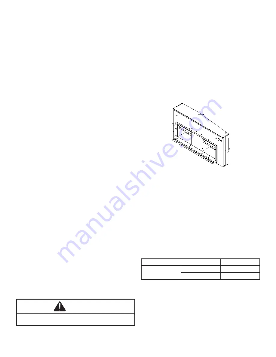
The supply ductwork flanges are shipped loose and
required to be field installed. See the following sketch for
further details: Dimensions are approximately 40” x 13-1/8”.
Return Ductwork
DO NOT TERMINATE THE RETURN DUCTWORK
IN AN AREA THAT CAN INTRODUCE TOXIC, OR
OBJECTIONABLE FUMES/ODORS INTO THE
DUCTWORK. The return ductwork is to be introduced into
the air handler bottom (upflow configuration). The cabinet
dimensions are 48” x 24”.
Return Air Filters
Each installation must include a return air filter. This unit
is factory equipped with disposable return air filters. To
ensure optimum performance, frequent filter replacement
is advised. See the following table for the factory installed
filter sizes.
Model
Filter Size (in)
Qty.
DAX0904 and
DAX1204
16 x 20 x 2
2
20 x 20 x 2
2
Electric Heat
Refer to this manual in combination with the instructions
provided with the heat kit for the correct installation
procedure.


