7
1 IM-5WMYJ-0113(2)DAIKIN_EN.indd9 9
1 IM-5WMYJ-0113(2)DAIKIN_EN.indd9 9
6/10/14 10:07:2 5 AM
6/10/14 10:07:2 5 AM
English
UNIT INSTALLATION
4
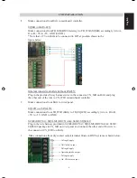
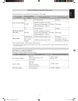
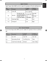
Make
connections
from
input
contacts
terminal
blocks
to
BMS
system
as
shown
below:
5
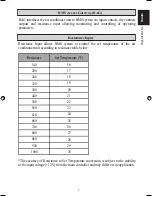
Make connections from resistance input terminal block to BMS system as shown
below:
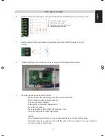
6
Adjust and align all wires to wire clips as shown in the image shown below:
7
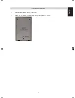
Decide the location to install the BAG.
Please consider the following precautions in your decision:
Do not install the unit in location that is:
• Exposed to direct sunlight.
• Susceptible to humidity and moisture.
• Near to heat source.
• Near to machines that emits high frequency wave.
• Near to high current switching devices.
Caution:
• Over-tightening the screws can cause deformation or/and crack at the casing.
• Mount the bottom casing on a wall with flat surface. Unit mounted on an uneven surface
can cause cracks at the casing.
S1: Force off control switch
S2: On/ Off control switch
S3: Operating mode control switch
S4: Fan speed control switch

