13 Disposal
Installer reference guide
77
EPGA11~ EA9W
Daikin Altherma – Low temperature split
4P556075-1 – 2019.02
INFORMATION
In case of an E7‑62 error, brine pump operation stops due
to not enough flow in the brine circuit. If 10‑day brine pump
operation is running, it will stop running and will only
resume once the error is reset. It is only possible to reset
the error with the domestic hot water home screen or the
leaving water temperature home screen turned ON. To
reset the error, press
and confirm by pressing
.
INFORMATION
If an U8‑04 error occurs, the error can be reset after a
successful update of the software. If the software is not
successfully updated then you must make sure that your
USB device has the FAT32 format.
INFORMATION
How an error code can be reset will be displayed on the
user interface connected on the indoor unit.
13
Disposal
NOTICE
Do NOT try to dismantle the system yourself: dismantling
of the system, treatment of the refrigerant, oil and other
parts MUST comply with applicable legislation. Units
MUST be treated at a specialised treatment facility for
reuse, recycling and recovery.
13.1
Overview: Disposal
Typical workflow
Disposing of the system typically consists of the following stages:
1
Pumping down the system.
2
Performing vacuum drying.
3
Bringing the system to a specialized treatment facility.
INFORMATION
For more details, see the service manual.
13.2
To pump down
DANGER: RISK OF EXPLOSION
Pump down – Refrigerant leakage.
If you want to pump
down the system, and there is a leak in the refrigerant
circuit:
▪ Do NOT use the unit's automatic pump down function,
with which you can collect all refrigerant from the
system into the outdoor unit.
Possible consequence:
Self-combustion and explosion of the compressor
because of air going into the operating compressor.
▪ Use a separate recovery system so that the unit's
compressor does NOT have to operate.
NOTICE
During pump down operation, stop the compressor before
removing the refrigerant piping. If the compressor is still
running and the stop valve is open during pump down, air
will be sucked into the system. Compressor breakdown or
damage to the system can result due to abnormal pressure
in the refrigerant cycle.
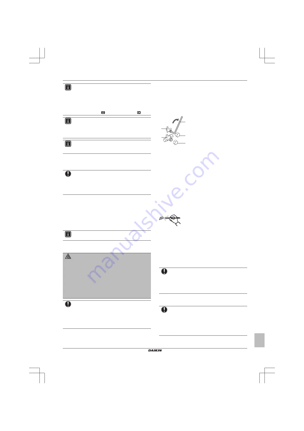
Pump down operation will extract all refrigerant from the system into
the outdoor unit.
1
Remove the valve lid from the liquid stop valve and the gas stop
valve.
2
Install a manifold on the gas stop valve.
3
After 5 to 10 minutes (after only 1 or 2 minutes in case of very
low ambient temperatures (<−10°C)), close the liquid stop valve
with a hexagonal wrench.
4
Check on the manifold if the vacuum is reached.
5
After 2-3 minutes, close the gas stop valve and stop forced
cooling operation.
a
c
b
d
d
e
a
Liquid stop valve
b
Closing direction
c
Hexagonal wrench
d
Valve lid
e
Gas stop valve
13.3
To activate/deactivate the vacuum
mode field setting
To perform vacuum drying of the outdoor unit’s internal refrigerant
piping it is necessary to activate the vacuum mode. This will open
required valves in the refrigerant circuit so the vacuuming process
can be done properly.
To activate vacuum mode:
Activating the vacuum mode is done by operating the BS1 push
button on the PCB (A1P). Operate the switches and push buttons
with an insulated stick (such as a closed ball-point pen) to avoid
touching of live parts.
When the unit is powered on and not running, push the BS1 push
button 3 times within a time frame of 10 seconds to activate vacuum
mode.
To deactivate vacuum mode:
After vacuuming the unit, please deactivate the vacuum mode by
pushing the BS1 push button 3 times within a time frame of 10
seconds.
Make sure to reattach the electronic component box cover and to
install the front cover after the job is finished.
NOTICE
Make sure that all outside panels, except for the service
cover on the electrical component box, are closed while
working.
Close the lid of the electrical component box firmly before
turning on the power.
13.4
To perform vacuum drying
NOTICE
▪ Connect the vacuum pump to
both
the service port of
the gas stop valve and the service port of the liquid
stop valve to increase efficiency.
▪ Make sure that the gas stop valve and liquid stop valve
are firmly closed before performing the leak test or
vacuum drying.
1
Vacuum the system until the pressure on the manifold indicates
−0.1 MPa (−1 bar).


