background image

Installation manual

5

4AMX80E7V3B

R410A Split series

4PW38479-1A

Refrigerant piping

1

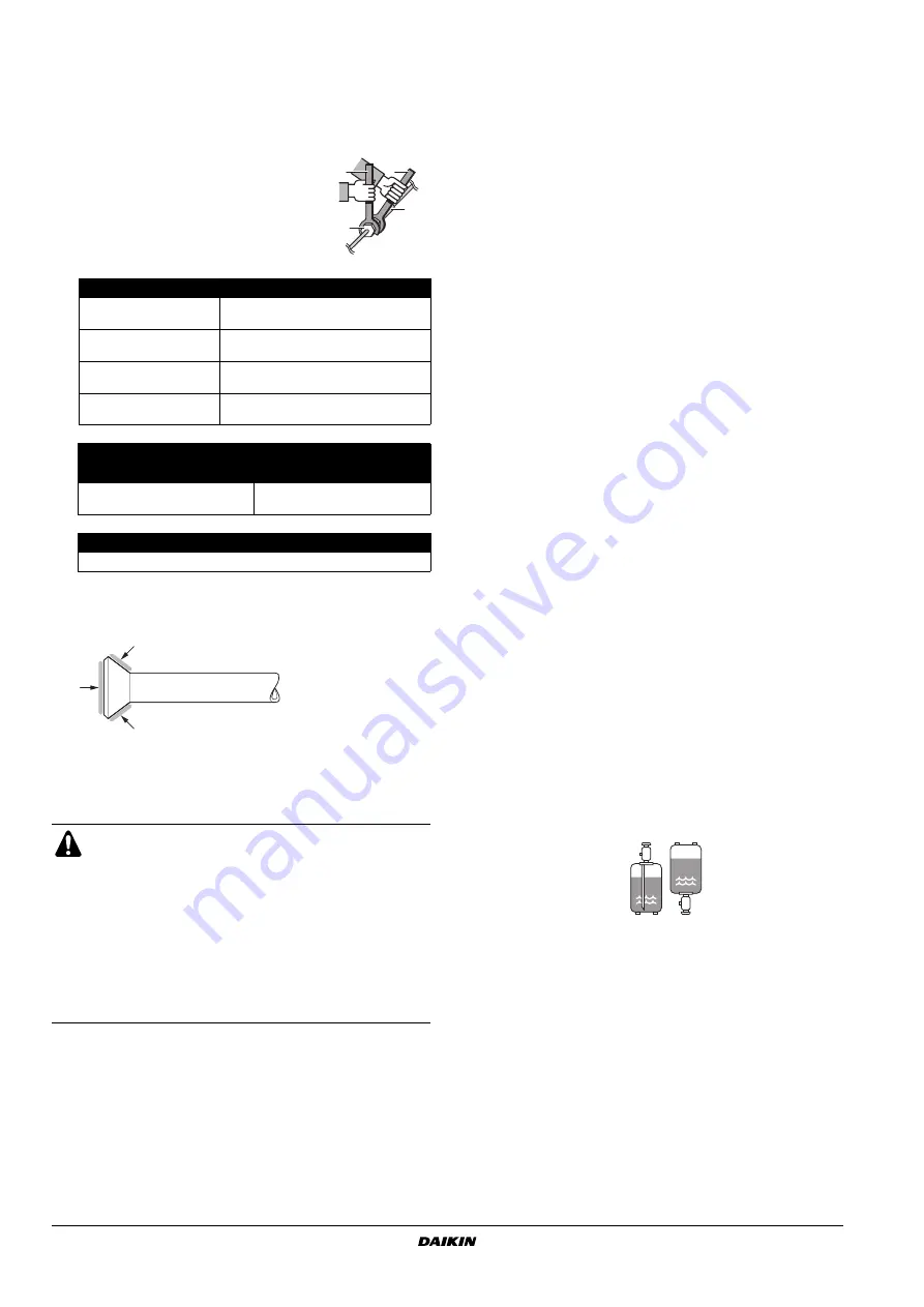
Align the centres of both flares and tighten the flare nuts 3 or 4
turns by hand. Then tighten them fully with torque wrenches.

Use torque wrenches when tightening the flare nuts to prevent
damage to the flare nuts and to prevent escaping of gas.

2

To prevent gas leakage, apply refrigeration machine oil on both
inner and outer surfaces of the flare (use refrigeration oil for
R410A).

Purging air and checking gas leakage

When piping work is completed, it is necessary to purge the air and
check for gas leakage.

If using additional refrigerant, perform air purging from the
refrigerant pipes and indoor unit using a vacuum pump, then
charge additional refrigerant.

Use a hexagonal wrench (4 mm) to operate the stop valve rod.

All refrigerant pipe joints should be tightened with a torque
wrench at the specified tightening torque.

1

Connect the projection side (on which the worm pin is pressed)
of the charging hose coming from the gauge manifold to the gas
stop valve’s service port.

2

Fully open the gauge manifold’s low-pressure valve (Lo) and
completely close its high-pressure valve (Hi). 

The high-pressure valve subsequently requires no operation.

3

Apply vacuum pumping. Check that the compound pressure
gauge reads –0.1 MPa (–760 mm Hg). 

Evacuation for  at least 1 hour  is recommended.

4

Close the gauge manifold’s low-pressure valve (Lo) and stop the
vacuum pump.  
Leave as is for 4-5 minutes and make sure the coupling meter
needle does not go back. 
If it does go back, this may indicate presence of moisture or
leaking from connecting parts. Repeat steps 2 – 4 after checking
all connecting parts and slightly loosening and retightening the
nuts.

5

Remove covers from liquid stop valve and gas stop valve.

6

Turn  the liquid stop valve’s rod 90 degrees counterclockwise
with a hexagonal wrench to open the valve. 

Close it after 5 seconds, and check for gas leakage.
Using soapy water, check for gas leakage from indoor unit’s flare
and outdoor unit’s flare and valve rods.  
After the check is complete, wipe all soapy water off.

7

Disconnect charging hose from gas stop valve’s service port,
then fully open liquid and gas stop valves. 

Do not attempt to turn valve rod beyond its stop.

8

Tighten valve lids and service port caps for the liquid and gas
stop valves with a torque wrench at the specified torques. See

"Refrigerant piping work" on page 4

 for details.

Charging refrigerant

This outdoor unit is factory charged.

In case re-charge is required, refer to the nameplate of the unit. The
nameplate states the type of refrigerant and necessary amount. 

Precautions when adding R410A

Be sure to charge the specified amount of refrigerant in liquid state to
the liquid pipe.

Since this refrigerant is a mixed refrigerant, adding it in gas form may
cause the refrigerant composition to change, preventing normal
operation.

Before charging, check whether the refrigerant cylinder is
equipped with a siphon tube or not.

Be sure to use tools exclusively for R410A to ensure required
pressure resistance and to prevent foreign materials from mixing
into the system.

1

Torque wrench

2

Spanner

3

Piping union

4

Flare nut

Flare nut

Flare nut tightening torque

Ø6.4

14.2~17.2 N•m

(144~175 kgf•cm)

Ø9.5

32.7~39.9 N•m

(333~407 kgf•cm)

Ø12.7

49.5~60.3 N•m

(505~615 kgf•cm)

Ø15.9

61.8~75.4 N•m

(630~769 kgf•cm)

Valve cap tightening torque

Liquid pipe

Gas pipe

26.5~32.3 N•m

(270~330 kgf•cm)

48.1~59.7 N•m

(490~610 kgf•cm)

Service port cap tightening torque

10.8~14.7 N•m (110~150 kgf•cm)

WARNING

Do not mix any substance other than the specified
refrigerant (R410A) into the refrigeration cycle.

When refrigerant gas leaks occur, ventilate the room
as soon and as much as possible.

R410A, as well as other refrigerants, should always
be recovered and never be released directly into the
environment.

Use a vacuum pump for R410A exclusively. Using the
same vacuum pump for different refrigerants may
damage the vacuum pump or the unit.

1

2

3

4

Charge the liquid 
refrigerant with the cylinder 
in upright position.

Charge the liquid 
refrigerant with the cylinder 
in up-side-down position.

Summary of Contents for 4AMX80E7V3B

Page 1: ...INSTALLATION MANUAL 4AMX80E7V3B R410A Split series ...

Page 2: ...cm 35 cm 1 2 3 4 7 8 6 15 m 2 15 m 2 7 5 m 1 7 5 m 1 1 2 3 A 1 2 3 4 2 1 L N 5 4 50 Hz 230 V A B 3 C D 1 D C B A 2 S102 S2 S52 A B C D ON SERVICE MONITOR S15 S10 S23 S24 S22 S21 S20 A A H05VV A B C D 3 4 P 1 2 3 4 5 6 7 ...

Page 3: ...er under forutssetning av at disse brukes i henhold til våre instrukser 13 vastaavat seuraavien standardien ja muiden ohjeellisten dokumenttien vaatimuksia edellyttäen että niitä käytetään ohjeidemme mukaisesti 14 za předpokladu že jsou využívány v souladu s našimi pokyny odpovídají následujícím normám nebo normativním dokumentům 15 u skladu sa slijedećim standardom ima ili drugim normativnim doku...

Page 4: ... fire Install the air conditioner on a solid base that can support the weight of the unit An inadequate base or incomplete installation may cause injury in the event the unit falls off the base Electrical work should be carried out in accordance with the installation manual and the national electrical wiring rules or code of practice Insufficient capacity or incomplete electrical work may cause el...

Page 5: ...air temperature remains below or around the freezing point for a few days the outdoor unit s drain may freeze If so it is recommended to install an electric heater in order to protect drain from freezing Tighten the flare nut according to the specified method such as with a torque wrench If the flare nut is tightened too hard the flare nut may crack after a long time and cause refrigerant leakage ...

Page 6: ... remains 20 mm above the foundation surface CAUTION When operating the air conditioner in a low outdoor ambient temperature be sure to follow the instructions described below To prevent exposure to wind install the outdoor unit with its suction side facing the wall Never install the outdoor unit at a site where the suction side may be exposed directly to wind To prevent exposure to wind install a ...

Page 7: ... figure 3 REFRIGERANT PIPING WORK Installing the outdoor unit When installing the outdoor unit refer to Precautions for selecting the location on page 2 and Indoor outdoor unit installation drawings on page 3 If drain work is necessary follow the procedures below Method for installing drain piping Use drain plug for drainage In cold areas do not use a drain hose with the outdoor unit Otherwise dra...

Page 8: ...eck for gas leakage from indoor unit s flare and outdoor unit s flare and valve rods After the check is complete wipe all soapy water off 7 Disconnect charging hose from gas stop valve s service port then fully open liquid and gas stop valves Do not attempt to turn valve rod beyond its stop 8 Tighten valve lids and service port caps for the liquid and gas stop valves with a torque wrench at the sp...

Page 9: ...eat insulation materials that will withstand this temperature Be sure to insulate both the gas and liquid piping and to provide insulation dimensions as below Use separate thermal insulation pipes for gas and liquid refrigerant pipes Flaring the pipe end 1 Cut the pipe end with a pipe cutter 2 Remove burrs with the cut surface facing downward so that the chips do not enter the pipe 3 Put the flare...

Page 10: ...ng See figure 5 WARNING Do not use mineral oil on flared part Prevent mineral oil from getting into the system as this would reduce the lifetime of the units Never use piping which has been used for previous installations Only use parts which are delivered with the unit Do never install a drier to this R410A unit in order to guarantee its lifetime The drying material may dissolve and damage the sy...

Page 11: ...ing electrical shock or fire Do not use locally purchased electrical parts inside the product and do not branch the power for the drain pump etc from the terminal block Doing this may cause electrical shock or fire Be sure to install an earth leakage breaker This unit uses an inverter which means that an earth leakage breaker capable of handling high harmonics needs to be used in order to prevent ...

Page 12: ...de Night quiet mode function The night quiet mode function reduces operating noise of the outdoor unit at nighttime This function is useful if the customer is worried about the effects of the operating noise on the neighbours Running units in night quiet mode however reduces the cooling heating capacity Setting procedure Remove the SW5 jumper switch Once the settings are complete reset the power C...

Page 13: ... During the test run first check the operation of each unit individually Then also check the simultaneous operation of all indoor units Check both heating and cooling operation After running the unit for approximately 20 minutes measure the temperatures at the indoor unit inlet and outlet If the measurements are above the values shown in the table below then they are normal During cooling operatio...

Page 14: ...ctly No cooling no heating Is the wiring in accordance with the specifications Operation failure burning Are the inlets outlets of the indoor and outdoor units free of any obstructions Are the stop valves open No cooling no heating Do the marks match room A room B on the wiring and piping for each indoor unit No cooling no heating Is the priority room setting set for 2 or more rooms The priority r...

Page 15: ...NOTES NOTES ...

Page 16: ...4PW38479 1A Copyright Daikin ...

Reviews: