


IM 1167
13
Installation and Startup
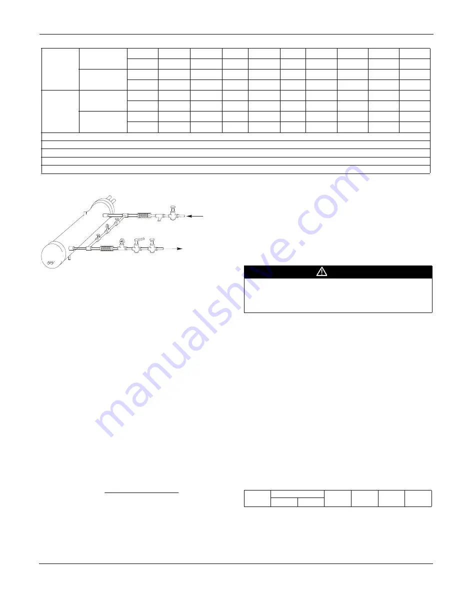
Figure 13: Typical Field Water Piping
Note:
Connections for vent and drain fittings are located on the top
and bottom of the evaporator.
Note:
Piping must be supported to avoid putting strain on the
evaporator nozzles.
Refrigerant Charge
All packaged units are designed for use with R-134a and are
shipped with a full operating charge. The operating charge for
each unit is shown in the Physical Data Tables beginning on
page 15
.
Glycol Solutions
When using glycol anti-freeze solutions, the chiller's capacity,
glycol solution flow rate, and pressure drop through the
evaporator can be calculated using the following:
Note:
The procedure below does not specify the type of
glycol. Use the derate factors found in
Table 5
or
Table 6
forcorrections when using glycol.
1
Capacity
- Cooling capacity is reduced from that with
plain water. To find the reduced value, multiply the
chiller’s water system tonnage by the capacity correction
factor to find the chiller’s capacity when using glycol.
2
Flow
- To determine flow (or Delta-T) knowing Delta-T
(or flow) and capacity:
3
Pressure drop
- To determine pressure drop through the
evaporator when using glycol, enter the water pressure
drop curve at the water flow rate. Multiply the water
pressure drop found there by the "PD" factor to obtain
corrected glycol pressure drop.
4
Power
- To determine glycol system kW, multiply the
water system kW by the factor designated "Power".
Test coolant with a clean, accurate glycol solution hydrometer
(similar to that found in service stations) to determine the
freezing point. Obtain percent glycol from the freezing point
table below. On glycol applications, the supplier normally
recommends that a minimum of 25% solution by weight be
used for protection against corrosion or that additional
inhibitors should be employed.
CAUTION
Do not use automotive grade antifreeze. Industrial grade glycols must
be used. Automotive antifreeze contains inhibitors that will cause
plating on the copper tubes within the chiller evaporator. The type and
handling of glycol used must be consistent with local codes.
Performance Adjustment Factors
AWS chiller units are designed to operate with leaving chilled
fluid temperatures of 20.0°F to 60.0°F (-6.7°C to 15.6°C).
Consult the local Daikin McQuay sales office for performance
outside these temperatures. Leaving chilled fluid temperatures
below 40°F (4.4°C) result in evaporating temperatures at or
below the freezing point of water and a glycol solution is
required. MicroTech III control inhibits compressor unloading
at leaving fluid temperatures below 30°F (-1°C).
Low fluid temperatures or high equipment room humidity may
require optional double evaporator insulation. The system
designer should determine its necessity. The use of glycol will
reduce the performance of the unit depending on its concentra-
tion. Take this into consideration during initial system design.
On glycol applications, the supplier typically recommends that
a minimum of 25% solution by weight be used for protection
against corrosion, or additional inhibitors will be required.
Min.
Adjst.
Flow
gpm
5.8
7.5
13.7
18.0
27.5
65.0
125.0
190.0
205.0
Lpm
1.3
1.7
3.1
4.1
6.2
14.8
28.4
43.2
46.6
No Flow
gpm
3.7
5.0
9.5
12.5
19.0
50.0
101.0
158.0
170.0
Lpm
0.8
1.1
2.2
2.8
4.3
11.4
22.9
35.9
38.6
Max.
Adjst.
Flow
gpm
13.3
19.2
29.0
34.5
53.0
128.0
245.0
375.0
415.0
Lpm
3.0
4.4
6.6
7.8
12.0
29.1
55.6
85.2
94.3
No Flow
gpm
12.5
18.0
27.0
32.0
50.0
122.0
235.0
360.0
400.0
Lpm
2.8
4.1
6.1
7.3
11.4
27.7
53.4
81.8
90.8
Table 4: Paddle Type Flow Switch Flow Rates
Note:
1
A segmented 3-inch paddle (1, 2, and 3 inches) is furnished mounted, plus a 6-inch paddle loose.
Note:
2
Flow rates for a 2-inch paddle trimmed to fit the pipe.
Note:
3
Flow rates for a 3-inch paddle trimmed to fit the pipe.
Note:
4
Flow rates for a 3-inch paddle.
Note:
5
Flow rates for a 6-inch paddle.
Vent
Drain
Gate
Valve
Water
Strainer
Vibration
Eliminator
Valved
Pressure
Gauge
In
Out
Protect All Field Piping
Against Freezing
Flow
Vibration
Eliminator
Flow
Switch
Balancing
Valve
Gate
Valve
Flow
Liquid
Suction
T
Delta
factor
flow
tons
GPM
24
Table 5: Ethylene Glycol Correction Factors
% E.G
Freeze Point
Capacity
Power
Flow
PD
o
F
o
C