


SMLC-213-154
38
6. Specification
6.1 Specification and intrinsic error
Input rating
Phase voltage input
Zero-phase voltage (EVT tertiary) AC110V,190V common use
3-phase voltage (EVT secondary) AC110/√3V 50/60Hz
EVT secondary:V(RN),V(SN),V(TN)
EVT tertiary :Vaf
Line voltage input
Zero-phase voltage (EVT tertiary) AC110V,190V common use
3-phase voltage (EVT secondary) AC110V 50/60Hz
EVT secondary:V(RS),V(ST),V(TR)
EVT tertiary :Vaf
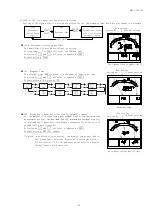
Measurement item
Measurement range /
Display specification (
26
)
Intrinsic error (
27
)
Note
Digital
display
Analog
output
Voltage
(Line voltage)
Instant(It is demand except Time interval
setting 0 second.), Maximum, Minimum
AC150V to 750.0kV (34 range)
±1.0%
±0.5%
Time interval measurement by
setting is possible.
RS-ST-TR line change
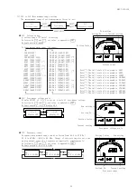
Zero-phase voltage
(
29
)
Instant, Maximum, Minimum
AC150V to 750.0kV (In voltage range)
±1.0%
±0.5%
Response time setting is
possible.
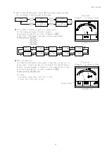
Ground fault phase
acknowledgement
function
(Phase voltage)
(
28
)(
30
)
Instant, Maximum, Minimum
AC150V to 750.0kV (In voltage range)
±1.0%
±0.5%
Ground fault phase is displayed
from a RN-SN-TN phase voltage at
the case of zero-phase voltage
detection. (
31
)
Response-time setting is
possible.
Frequency
Instant, Maximum, Minimum
45.0 to 55.0Hz or
55.0 to 65.0Hz or
45.0 to 65.0Hz (Range select)
±0.5%
±0.5%
0.0Hz in case input is below 20%
of voltage range.
Operating system
Voltage :Effective value computing type.
Demand voltmeter (Line voltage):Computing type according with bimetallic type.
Zero-phase voltage,Ground fault phase detection:Fundamental-wave effective-value computing type
Frequency:Zero cross cycle computing type.
Response time
setting
Maximum zero-phase
voltage
Ground fault phase
detection
0.05 seconds / 0.1 seconds / 0.15 seconds / 0.2 seconds / 0.5 seconds /
1 second / 2 seconds / 3 seconds / 5 seconds
(90% response)
Time interval
setting
Voltage
0 second / 5 seconds / 10 seconds / 20 seconds / 30 seconds / 40 seconds /
50 seconds / 1 minute / 2 minutes / 3 minutes / 4 minutes / 5 minutes /
6 minutes / 7 minutes / 8 minutes / 9 minutes / 10 minutes / 15 minutes /
20 minutes / 25 minutes / 30 minutes (95% time limit)
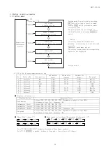
Bar graph display
Bar graph display of the main-monitor factor is done.
A display of a sub-monitor factor can also be set.
Option
Analog output (4 sets), Alarm output (2 sets), External operation change input (2 sets)
Note(
26
) The instantaneous value of each measurement factor can be checked by instantaneous measurement display.
And, about the maximum value and the minimum value, it can check by the maximum and the minimum measurement
display.
However, about a maximum zero-phase voltage, it can check by instantaneous measurement display.
Note(
27
)
When the inverter output is directly measured in cycle control, SCR phase angle control, or PWM control,
an error increases due to the operation principle.
Note(
28
) The line voltage input product is display OFF.
Note(
29
)
When you measure zero-phase voltage, please be sure to perform connection of 3-phase voltage.
In measurement of only a zero-phase voltage, an error becomes large.
Note(
30
)
After an operation start, the maximum value reset and minimum value reset is needed. (By DI or switch
operation)
Note(
31
)
A ground fault phase constitutes the minimum phase of RN-SN-TN phase voltage.
However, if a high order circuit breaker is OFF at the case of zero-phase voltage detection, all the
minimum value of RN-SN-TN will be set to 0V. In that case, please check a ground fault phase at the
maximum value of RN-SN-TN phase voltage.


