24
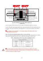
Fig.25
Schematic drawing of the controller external wiring connections (for one engine)
Connect the sensor wires on the [ENGINE A SENSOR] side when one engine is involved.
Connect the sensor wires respectively with the [ENGINE A SENSOR] for one engine and with the
[ENGINE B SENSOR] for another engine when two engines are involved.
Always pull the shielded-conductor cable out and connect it with the grounding bar installed in front of
the terminal block inside the controller for sensor wires.
Always connect the grounding wire with the grounding terminal at the lower right side inside the
controller frame for grounding the system.
The terminal block is of the clamp type. See the wiring instruction manual to correctly wire the
controller.
Do not connect to the [OPTION EX. MONITOR] and the [OPTION] terminals.
Isolate wires for the controller from those for the motor, and solenoid valves and for the power supply
lines to prevent noise impacts.
As various sizes of marine use gland packing suitable for the wiring are supplied with the detector, use
the correct size gland packing.
Refer to the next chapter to set the wire disconnection detecting resistor if the resistor is required to
detect disconnection in the alarm setting off wire as the wire disconnection detecting resistor is installed
in the control unit.
Note)
The drain wire of shielded cable for communication line to the sensors must be connected the
grounding bar. The ground wire for power line must be connected to ground terminal.
Otherwise
the detecting performance may be deteriorated.
※
Please minimize to less than 100mm
for the length of single cable including shield Cable
which exposes from outer skin.
Wiring
for sensors
Contact
Outputs
Power supply
line
* The drain wire of
shielded cable must be
installed to the
grounding bar.
* Ground wire must
be installed to the
ground terminal
Original content from www.daihatsu.cc
Issued to HORIZON TANKERS LIMITED S.A.


