22
9.2
Wiring of the sensor
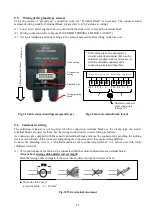
(1) Cable for connection : Daihatsu option cables
[Cable with both-ends connector] or [Cable with single-sided connector]
(2) Connection topology : Daisy chain
(3) Connection method : Connector - Connector
<Before connection>
<After connection>
(The terminal in the sensor)
Cable connection diagram of connecter type
Fig. 23 Connection of sensor and wiring (Connector)
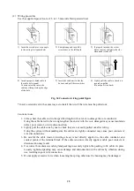
(4) Connection method of connectors
The connectors have polarity.
The sensor side is female connector.
The wiring side is male connector.
1) The connectors have a position to fit.
Connect the cable connector to the sensor connector while checking that the inner pins of the cable
connector can be inserted into the holes of the sensor connector.
Notes) Please do not look for the fit position after putting connectors together.
The connector pins may be broken, and the broken pins may cause imperfect contact.
2) Tighten a cable side fixing ring with your hand enough.
After tightening, there will be a gap of approximately 1 to 2 mm between the sensor connector and the
cable connector. This gap will not cause any problems.
Notes) Please set the termination and node settings to the sensors necessarily after wiring work was
over. And attach a dust cover (option) to an unused connector of a sensor unit of end.
Sensor connector
It fastens a cable side
and is a lump ring.
Cable connector
Cable
Gap
(approx. 1 to 2 mm)
1
2
3
4
+24V
0V
S + S -
A
5
6
7
8
+24V
0V
S + S -
B
Cable connection diagram of connecter type
Brown
Blue
White
Black
Brown
Blue
White
Black
Female connector
Male connector
Fig. 24 CONNECTOR FORM
Original content from www.daihatsu.cc
Issued to HORIZON TANKERS LIMITED S.A.


