Dahua TPC-KF2241-T Quick Start Manual Download Page 17


11 

5 Alarm Configuration 

The Camera can link to alarm output devices to report alarms when alarms are triggered from 
external alarm input devices. 


Cut off the power before connecting the cables. 
Step 1 

Connect the alarm input device to the alarm input port of I/O cable. 
Alarm input: Receives on-off signals from external alarm devices, and supports NO and NC 
alarm input. The input signal is idle or grounded, and the Camera can collect different 
states of the alarm input port. 

  When the input signal is 3.3 V or idle, the Camera collects logic "1". 

  When the input signal is grounded, the Camera collects logic "0". 

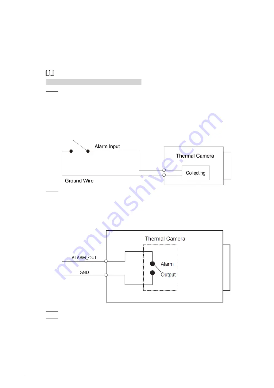
Figure 5-1 Alarm input 


Step 2 

Connect the alarm output device to the alarm output port of I/O cable. 
Alarm output: Port ALARM_OUT and GND form a switch to provide alarm output. The 
switch is normally on and has a high resistance. ALARM_OUT is connected to ground when 
there is an alarm output. 

Figure 5-2 Alarm output 


Step 3 

Log in to the web interface, and then select 

Setting

 > 

Event

 > 

Alarm

Step 4 

On the 

Alarm

 page, configure settings for alarm input and output, and then click 

Save

  In the 

Relay-in

 list, select the alarm input port of I/O cable. Set the 

Sensor Type

 as 

NO


if the alarm input device generates high electrical levels when an alarm occurs, and 

NC


if it generates low electrical levels. 

  In the 

Relay-out

 list, select the alarm output port of I/O cable. 

Summary of Contents for TPC-KF2241-T

Page 1: ...Thermal Network Hybrid Thermography Cube Camera Quick Start Guide V1 0 0...

Page 2: ...cy protection laws and regulations to protect the legitimate rights and interests of other people by implementing measures which include but are not limited Providing clear and visible identification...

Page 3: ...ftware if the manual in PDF format cannot be opened All trademarks registered trademarks and company names in the manual are properties of their respective owners Please visit our website contact the...

Page 4: ...mergency power off when necessary Prevent the line cord from being trampled on or squeezed especially the plug power socket and the junction from the Camera Application Environment Requirements Please...

Page 5: ...then softly wipe the dirt away Clean the Camera body with a piece of soft dry cloth For any dirt that is hard to remove pick up a piece of clean and soft cloth dip it into a little neutral detergent...

Page 6: ...5 3 3 Live Video 5 4 Installation 7 4 1 Preparations 7 4 1 1 Checking Installation Space and Intensity 7 4 1 2 Cable Preparation 7 4 2 Installing Camera 8 4 2 1 Restoring to Default Settings 8 4 2 2 I...

Page 7: ...he installation process do not come with the delivery Please buy them if they are needed Keep accessories safe for future use Figure 1 1 Checklist Table 1 1 Checklist No Name Quantity No Name Quantity...

Page 8: ...2 2 Design 2 1 Dimensions Figure 2 1 Component dimensions mm inch 2 2 Cables The following figure of the cable is for reference only and might differ from the actual product...

Page 9: ...nputs 12 VDC Supply power to the device according to the label to avoid damages to the Camera 3 RS 485 RS 485 port Connects to external RS 485 devices 4 ALARM_OUT Alarm output port Alarm devices such...

Page 10: ...t a time log in to the web interface Initialize the device for first time use after performing a factory reset To keep the data on the Camera secure keep the admin password safe after initialization a...

Page 11: ...re 3 2 TCP IP Step 3 Configure IP related parameters Step 4 Click Save 3 3 Live Video The web interface might differ depending on the device Figures in this guide are for reference only Step 1 Log in...

Page 12: ...install a plug in for first time system login Please download and install the plug in The web interface will refresh automatically after the plug in is installed and then the live video will be displa...

Page 13: ...eparation Power Cord To extend the power cord you have received evaluate the distance you want to extend to and then select the appropriate cord diameter Table 4 1 Power cord description Distance ft m...

Page 14: ...on for more than 10 s to reset the Camera to factory settings Figure 4 1 Component Network indicator It flashes orange when the network is connected Power indicator Before the Camera starts it is red...

Page 15: ...Paste the positioning map Choose a suitable mounting surface and then paste the positioning map to the surface Drill the holes according to the label signs Figure 4 3 Paste the positioning map Step 2...

Page 16: ...10 Figure 4 4 Secure the Camera Step 3 Remove the label After attaching the Camera to the mounting surface remove the label from the lens Figure 4 5 Remove the label...

Page 17: ...Camera collects logic 0 Figure 5 1 Alarm input Step 2 Connect the alarm output device to the alarm output port of I O cable Alarm output Port ALARM_OUT and GND form a switch to provide alarm output T...

Page 18: ...12 Figure 5 3 Alarm setting...

Page 19: ...ounding bar on the tower connect the Camera grounding wire to the bar If there is no grounding bar use multiple copper cable whose cross sectional area are not less than 16 mm to connect the Camera gr...

Page 20: ...14 Figure 1 1 Lightening protection...

Page 21: ...cabinet and implement well done access control permission and key management to prevent unauthorized personnel from carrying out physical contacts such as damaging hardware unauthorized connection of...

Page 22: ...we suggest that you check online users regularly to see if the device is logged in without authorization Check device log By viewing the logs you can know the IP addresses that were used to log in to...

Reviews: