background image


SN 

Note 

Icon 

Button Name 

Function  

to stop. 

PATTERN 

Pattern  


Set mode: Click

PATTERN

is to go to 

setup interface. 


Use mode: For example, 5+

PATTERN

is to call pattern No.5 and then click the 

PATTERN

to stop. 

3D 
Joystick 

Aux menu and function operation.  

Indicator 
light 
panel 

PWR 

Power indicator 
light  

The light is on when the keyboard is properly 
connected to the power supplying.  

TR/TX 

Network data 
receive and 
send indicator 
light  

The light is flashing when the keyboard is 
connected to the network.  

NET 

Network 
indicator light  

The light is on when the device is connected to 
the network.  

232 

RS232 indicator 
light  

The light is flashing when there is 232 data 
transmission.  

485 

RS485 indicator 
light 

The light is flashing when there is 485 data 
transmission. 

USB 

USB indicator 
light  

The light is on when the keyboard is connected 
to the USB device.  


For network keyboard, the light is on when 
the keyboard is connected to the PC.  


For analog keyboard and speed dome 
keyboard, the light is on when the keyboard 
is connected to the USB device.  

LCD 

OSD menu 


1.3


Rear Panel 

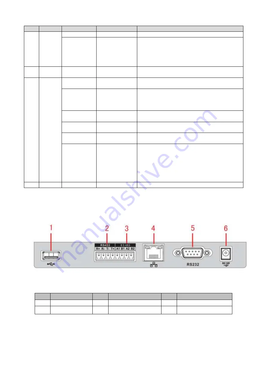
1.3.1  Network Keyboard Series  

Please refer to Figure 1-2  for network keyboard port information.  


Figure 1-2 

Please refer to the following sheet for detailed information.  

SN 

Port Name 

SN 

Port Name 

SN 

Port Name 

USB port 

RS422 port 

RS485 port 

Network port 

RS232 port 

Power socket 


1.3.2  Analog Keyboard Series  

Please refer to Figure 1-3  for analog keyboard port information.  

Summary of Contents for NKB Series

Page 1: ...Keyboard Quick Start Guide Version 1 1 1...

Page 2: ...4 1 5 Power 4 2 Menu Operation 5 2 1 Boot up and Shut down 5 2 1 1 Boot up 5 2 1 2 Shut Down 5 2 2 Main Menu List 5 2 3 Menu Operation 7 2 3 1 System 7 2 3 2 Zone Control Point 9 2 3 3 Account 10 2 3...

Page 3: ...5 1 Splicing Screen Control 21 5 2 Output Video to the TV wall 23 5 3 Zone Settings via the Keyboard 23 6 Network Keyboard to Control Analog Matrix 24 6 1 Analog Matrix Operation 24 6 2 Keyboard Oper...

Page 4: ...iii 8 4 RJ45 Network Port Connection 29...

Page 5: ...sing our keyboard This quick start guide is designed to be a reference tool for the operation of your system Before the operation please read the following safeguards and warnings carefully Please kee...

Page 6: ...re designed to provide reasonable protection against harmful interference in a commercial environment Operation of this equipment in a residential area is likely to cause harmful interference in which...

Page 7: ...ied engineers needed All the examination and repair work should be done by the qualified service engineers We are not liable for any problems caused by unauthorized modifications or attempted repair 5...

Page 8: ...nconsistency between paper User s Manual and the electronic version the electronic version shall prevail All the designs and software are subject to change without prior written notice The product upd...

Page 9: ...DVRs s menu setup On screen menu user friendly procedure It is very easy for you to operate Besides above mentioned features network keyboard also has the following features Can control network video...

Page 10: ...pen DVR local PTZ interface FN Function key Work with the number buttons FN 1 Go to DVR assistant interface FN 2 Tour FN 3 Electronic zoom PTZ Window PTZ button Control channel PTZ Select specified wi...

Page 11: ...t is flashing when there is 232 data transmission 485 RS485 indicator light The light is flashing when there is 485 data transmission USB USB indicator light The light is on when the keyboard is conne...

Page 12: ...sheet for detailed information SN Port Name SN Port Name SN Port Name SN Port Name 1 USB port 2 RS422 port 3 RS485 port 4 Power socket 1 4 Port Features RS232 port can directly connect to device if t...

Page 13: ...the up down left right to Input user name and password system goes to the main menu Note Factory default user names are admin default guest The password is 888888 The default can not add delete user...

Page 14: ...6 Figure 2 2...

Page 15: ...p aux setup system update and logo update See Figure 2 3 Figure 2 3 2 3 1 1 Time It is to set keyboard system time It includes year month date minute and second See Figure 2 4 Figure 2 4 2 3 1 2 Netwo...

Page 16: ...ole process Otherwise it may result in upgrade failure and the network keyboard can not boot up properly The flash disk upgrade function is for speed dome keyboard or analog keyboard series product Yo...

Page 17: ...pgrade file 5 Click the button Bios at the bottom of the interface you can complete the upgrade process 2 3 1 6 Logo update The logo upgrade function is for speed dome keyboard or analog keyboard seri...

Page 18: ...ntrolled device to set the user name and password The DVR and NVR have the rights management to realize password verification 2 3 3 Account Here is for you to change password add user and delete user...

Page 19: ...item and then use the joystick to move the left right to turn to to enable this function See Figure 2 14 Figure 2 14 Note Please go to the controlled device to set rights 2 3 3 3 Delete Users Select a...

Page 20: ...rt the configuration files 2 3 4 3 Clear Zones Go to the clear zones interface and then click ENTER to clear all control points 2 3 4 4 Default Go to the default interface and then click ENTER to rest...

Page 21: ...pops up a dialogue box you can click ENTER to save data or click ESC to cancel setup 3 3 Operation On the keyboard click ID to go to the control point interface to set speed dome ID to connect to the...

Page 22: ...et you can set a preset quickly On the Use mode use keyboard to input No Preset you can set a preset quickly General Mode On the keyboard click PRESET the interface is shown as below See Figure 3 2 Fi...

Page 23: ...then click ENTER system stops scan 3 3 5 Pan Shortcut Mode On the Use mode click Pan button on the keyboard the speed dome begins pan Click Pan again to stop it General Mode On Set mode click PAN butt...

Page 24: ...and then select PresetDel click ENTER button to delete the input preset from the tour Note You can add several presets to add to a tour 3 3 6 2 Call tour Select Start and then click ENTER speed dome...

Page 25: ...n click ENTER to end The speed dome can memorize your whole operation 3 3 7 2 Start pattern Select pattern No and then input a pattern number select start and then click ENTER button system begins pat...

Page 26: ...col is network keyboard protocol d After the setup click ESC to exit control point control interface System pops up a dialogue box you can click ENTER to save data or click ESC to cancel setup 4 1 2 N...

Page 27: ...17 32 Up down DVR split in 1 4 9 or 25 32 No CAM Select corresponding channel Input 9 and then click CAM button the DVR displays the video from channel 9 No PTZ Control the PTZ of the corresponding d...

Page 28: ...20 SN Function SN Function SN Function by frame...

Page 29: ...Figure 5 2 Click Fast splicing button you can realize 1 1 setup conveniently For the network keyboard it support 2 2 and etc splicing setup Please follow the steps listed below 1 Click Fast splicing...

Page 30: ...igure 5 2 click Info manager button you can view and edit the corresponding screen control SN For network keyboard click the Control ID PLAY one by one you can select the output screen quickly See Fig...

Page 31: ...lick the edit button you can edit the correspondong control SN See Figure 5 4 For network keyboard click the Control ID CAM you can output the video to the TV wall Figure 5 4 5 3 Zone Settings via the...

Page 32: ...CH OK on the matrix screen 2 Check the parameter setups Click Menu 1 one by one check the baud rate setup of the matrix is OK or not Click Menu 2 one by one check the RS232 address of the matrix is th...

Page 33: ...nding decoded slot and then click Save Follow the steps listed below to control the splicing screen 1 Click Splice 2 CTRL Left click mouse to select several screens at the same time 3 Click OK to spli...

Page 34: ...26 For network keyboard click the Control ID CAM one by one you can output the video on the wall to preview Figure 7 2...

Page 35: ...27 Figure 7 3 7 3 Zone Settings via the Keyboard Please refer to chapter 2 3 2 Zone control point for detailed information The device type is DVM and step default value is 64...

Page 36: ...Com adopts the crossover connection mode 2 3 3 2 5 5 Crossover connection mode is shown as in Figure 8 2 Figure 8 2 8 2 Make RS485 COM Cable Note RS232 port can only connect to one DVR If you want to...

Page 37: ...GND and TXD Please refer to the following figure if you are connecting 485 switch box to DVR See Figure 8 4 Note 485 232 switch box does not need the TXD cable The 1 to 8 COM port already supports th...

Page 38: ...ght difference may be found in the user interface All the designs and software here are subject to change without prior written notice All trademarks and registered trademarks mentioned are the proper...

Reviews: