background image

6

 'HYLFH,QVWDOODWLRQ

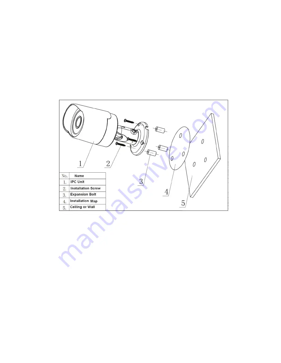
Please follow the steps listed below to install the device.  Please refer to Figure 3-1 and Figure 3-2  for 

reference. 

z


Paste the installation map on the surface of the wall or the ceiling. 

z


Dig the installation holes according to the installation map.  

z


Open the accessories bag and then take the expansion bolt out. Insert the expansion bolt into 

the installation holes. 

z


Take the screws from the accessories bag and then use them to secure the device on the 

installation surface of the wall or the ceiling. 

z


Connect the corresponding cables. 

Figure 3-1 

z


Use the cross-head screwdriver to loosen the adjust screw. 

z


Turn the device in different directions to make it suitable for the monitor position. 

z


Use the cross-head screwdriver to fix the adjust screw firmly. 

Summary of Contents for IPC-HFW2100N Series

Page 1: ...Cost effective HD IR Waterproof Fixed IP Camera Quick Start Guide Version 1 0 1...

Page 2: ...ion security Heavy stress violent vibration or water splash are not allowed during transportation storage and installation 3 Installation Do not apply power to the camera before completing installatio...

Page 3: ...vice If there is too much dust please use the water to dilute the mild detergent first and then use it to clean the device Finally use the dry cloth to clean the device Please put the dustproof cap to...

Page 4: ...le of Contents UDPHZRUN 1 0XOWLSOH IXQFWLRQ RPELQDWLRQ DEOH 1 UDPHZRUN DQG LPHQVLRQ 1 HYLFH QVWDOODWLRQ 3 4XLFN RQILJXUDWLRQ 7RRO 5 2YHUYLHZ 5 2SHUDWLRQ 5 4 8 SSHQGL 7R LF RU D DUGRXV 0DWHULDOV RU OHP...

Page 5: ...Please refer to the following sheet for detailed information Port Name Function Connection Note 1 LAN Network port Ethernet port Connect to standard Ethernet cable 2 DC12V Power input port Power inpu...

Page 6: ...2 Figure 1 3...

Page 7: ...s bag and then take the expansion bolt out Insert the expansion bolt into the installation holes z Take the screws from the accessories bag and then use them to secure the device on the installation s...

Page 8: ...4 Figure 2 2...

Page 9: ...dress and etc Figure 3 1 Select one IP address and then right click mouse you can see an interface is shown as in Figure 3 2 Note You can set the IP address subnet mask and gateway for the IPC and PC...

Page 10: ...IP address and then double click it to open the login interface Or you can select an IP address and then click the Login button to go to the login interface See Figure 3 4 In Figure 3 4 you can view d...

Page 11: ...uration tool main interface is shown as below See Figure 3 5 Figure 3 5 For detailed information and operation instruction of the quick configuration tool please refer to the Quick Configuration Tool...

Page 12: ...t install the client end or can not view after the installation We recommend the win2000sp4 OS or install the client end of the low version The Active X control is blocked The display card version sha...

Page 13: ...y use period EFUP period the toxic or hazardous substance or elements contained in products will not leak or mutate so that the use of these substances or elements will not result in any severe enviro...

Page 14: ...Cost effective HD IR Waterproof Fixed IP Camera User s Manual Version 1 0 2...

Page 15: ...our IP camera This user s manual is designed to be a reference tool for your system Please read the following safeguard and warnings carefully before you use this series product Please keep this user...

Page 16: ...wer cut off device during the installation connection Always follow the instruction guide the manufacturer recommended 4 Qualified engineers needed All the examination and repair work should be done b...

Page 17: ...evice Finally use the dry cloth to clean the device Please put the dustproof cap to protect the CCD CMOS component when you do not use the camera 7 Accessories Be sure to use all the accessories recom...

Page 18: ...RQ 1 2YHUYLHZ 1 HDWXUHV 1 6SHFLILFDWLRQV 2 6WUXFWXUH 4 0XOWLSOH IXQFWLRQ RPELQDWLRQ DEOH 4 UDPHZRUN DQG LPHQVLRQ 4 HYLFH QVWDOODWLRQ 6 4XLFN RQILJXUDWLRQ 7RRO 8 2YHUYLHZ 8 2SHUDWLRQ 8 4 11 SSHQGL 7R L...

Page 19: ...ckup function in accordance with your configuration and setup in alarm or schedule setting z Support record via Web and the recorded file are storage in the client end PC z Support network storage fun...

Page 20: ...5fps Video Frame Rate NTSC Main stream 1280 960 15fps extra stream 352 240 15fps Main stream 1280 720 30fps extra stream 352 240 30fps Video Bit Rate H 264 56Kbps 8192Kbps MJPEG is adjustable and bit...

Page 21: ...Remote Operation Monitor system setup file download log information maintenance upgrade and etc Restore Default Setup Reset button Network IR light 30 LED IR light 20 30M Power DC12V power and PoE Po...

Page 22: ...2 1 Please refer to the following sheet for detailed information Port Name Function Connection Note 1 LAN Network port Ethernet port Connect to standard Ethernet cable 2 DC12V Power input port Power i...

Page 23: ...5 Figure 2 2 Figure 2 3...

Page 24: ...s bag and then take the expansion bolt out Insert the expansion bolt into the installation holes z Take the screws from the accessories bag and then use them to secure the device on the installation s...

Page 25: ...7 Figure 3 2...

Page 26: ...dress and etc Figure 4 1 Select one IP address and then right click mouse you can see an interface is shown as in Figure 4 2 Note You can set the IP address subnet mask and gateway for the IPC and PC...

Page 27: ...IP address and then double click it to open the login interface Or you can select an IP address and then click the Login button to go to the login interface See Figure 4 4 In Figure 4 4 you can view d...

Page 28: ...guration tool main interface is shown as below See Figure 4 5 Figure 4 5 For detailed information and operation instruction of the quick configuration tool please refer to the Quick Configuration Tool...

Page 29: ...ot install the client end or can not view after the installation We recommend the win2000sp4 OS or install the client end of the low version The Active X control is blocked The display card version sh...

Page 30: ...environmental friendly use period EFUP period the toxic or hazardous substance or elements contained in products will not leak or mutate so that the use of these substances or elements will not resul...

Page 31: ...IPC Web Operation Manual Version 3 0 0...

Page 32: ...QX 5 9LGHR LQGRZ XQFWLRQ 2SWLRQ 5 9LGHR LQGRZ 6HWXS 6 37 RQWURO 8 6HWXS 11 DPHUD 11 4 1 1 Conditions 11 4 1 2 Video 14 4 1 3 Audio 18 1HWZRUN 19 4 2 1 TCP IP 19 4 2 2 Connection 21 4 2 3 PPPoE 23 4 2...

Page 33: ...tion 43 4 4 3 Record control 45 6 VWHP 46 4 5 1 General 46 4 5 2 Account 49 4 5 3 PTZ 53 4 5 4 Default 53 4 5 5 Import Export 54 4 5 6 Auto maintenance 54 4 5 7 Firmware update 55 QIRUPDWLRQ 55 4 6 1...

Page 34: ...ystem configuration alarm and etc Please follow the steps listed below for network connection z Make sure the IPC has connected to the network properly z IPC IP address and PC IP address shall be in t...

Page 35: ...8 then please input http 192 168 1 108 in IE address bar See Figure 2 1 Figure 2 1 IE The login interface is shown as below See Figure 2 2 Please input your user name and password Default factory name...

Page 36: ...b or not Please click OK button system can automatically install the control When system is upgrading it can overwrite the previous Web too If you can t download the ActiveX file please check whether...

Page 37: ...or window See Figure 2 4 Figure 2 4 Live Interface There are four sections z Section 1 Encode setup bar z Section 2 System menu z Section 3 Window function option bar z Section 4 Window adjust bar QFR...

Page 38: ...dropdown list There are three options TCP UDP Multicast 6 VWHP 0HQX System menu is shown as in Figure 2 6 Please refer to chapter 2 2 Live chapter 3 PTZ chapter 4 Setup chapter 5 Alarm chapter 6 Log...

Page 39: ...u can go to Setup Camera Audio to set bidirectional talk mode 9LGHR LQGRZ 6HWXS The interface is shown as in Figure 2 8 Figure 2 8 Video Window Setup Please refer to the following sheet for detailed i...

Page 40: ...It is to adjust monitor video contrast ness It is to adjust monitor video saturation It is to adjust monitor video hue Video setup Reset Restore brightness contrastness saturation and hue to system de...

Page 41: ...tour pan scan pattern aux close and PTZ setup button See Figure 3 1 z PTZ direction PTZ supports eight directions left right up down upper left upper right bottom left bottom right z Speed The step 8...

Page 42: ...move the camera to your desired location and then input preset value Click add button you have set one preset The preset value ranges from 1 to 80 It may vary due to different protocols Tour z Input a...

Page 43: ...Now you have set one pattern Assistant The assistant items include BLC Digital zoom night vision camera brightness flip You can select one option and then click start or stop button Matrix Please sel...

Page 44: ...rmation Parameter Function Brightness It is to adjust monitor window bright The value ranges from 0 to 100 The default value is 50 The larger the number the bright the video is When you input the valu...

Page 45: ...is This value has no effect on the general brightness of the whole video The video color may become too strong if the value is too high For the grey part of the video the distortion may occur if the...

Page 46: ...d of the white balance is in the sunny mode z Night The threshold of the white balance is in the night mode z Customized You can set the gain of the red blue channel The value reneges from 0 to 100 Da...

Page 47: ...cludes general stream motion stream and alarm stream You can select different encode frame rates form different recorded events System supports active control frame function ACF It allows you to recor...

Page 48: ...options VBR and CBR Please note you can set video quality in VBR mode Recommended Bit Recommended bit rate value according to the resolution and frame rate you have set Bit Rate z In CBR the bit rate...

Page 49: ...re are multiple resolutions You can select from the dropdown list For each resolution the recommended bit stream value is different Frame Rate PAL 1 25f s NTSC 1 30f s The frame rate may vary due to d...

Page 50: ...activation Image size It is the same with the resolution of the main stream Quality It is to set the image quality There are six levels Interval It is to set snapshot frequency The value ranges from 1...

Page 51: ...el Title z You can enable this function so that system overlays channel information in video window z You can use the mouse to drag the channel tile position 4 1 2 4 Path The storage path interface is...

Page 52: ...here to enable audio function Sub Extra stream Recorded file only contains video by default You need to check the audio box here to enable audio function Encode mode The encode mode of the main stream...

Page 53: ...vice needs to reboot to activate the new setup once you modify the default setup Mode There are two modes static mode and the DHCP mode z The IP submask gateway are null when you select the DHCP mode...

Page 54: ...e LAN This function is on by default You can refer to the steps listed below Step 1 Get an IP address Set the IPC and the PC in the same LAN Step 2 Get the physical address from the label of the IPC S...

Page 55: ...lue is 80 You can input the actual port number if necessary RTSP port The default value is 554 Rtsp streay query format is Main stream rtsp username password ip port cam realmonitor channel 1 subtype...

Page 56: ...t the IP address in the WAN from the IP address column Please note you need to go to the IP address item to via the device current device information You can access the client end via this address Fig...

Page 57: ...t Domain Name Your self defined domain name User The user name you input to log in the server Password The password you input to log in the server Update period z Device sends out alive signal to the...

Page 58: ...25 Figure 4 11 4 2 6 SMTP e mail The SMTP interface is shown as in Figure 4 12 Figure 4 12...

Page 59: ...conds 0 means there is no interval Please note system will not send out the email immediately when the alarm occurs When the alarm motion detection or the abnormity event activates the email system se...

Page 60: ...PnP User Interface Please click OK to begin installation Enable UPnP from the Web If your UPnP is enabled in the Windows OS the IPC can auto detect it via the My Network Places Figure 4 13 4 2 8 SNMP...

Page 61: ...hip between one proxy and one group of the managers Please make sure the device and the proxy are the same The read community will read all the objects the SNMP supported in the specified name The def...

Page 62: ...service information and listen to the service information from other device You can use the browse of the Bonjour service in the same LAN to search the IPC device and then access if you do not know th...

Page 63: ...of the group member and group of the outer Here you can set multicast address and port You also need to go to Live interface to set the protocol as Multicast Figure 4 16 4 2 11 WIFI Please note this...

Page 64: ...7 Please check the box to enable WIFI function and then click the Search SSID button Now you can view all the wireless network information in the following list Double click a name to connect to it Se...

Page 65: ...We can guarantee the transmission bandwidth lower the delay reduce the loss of the data packet and anti dither to enhance the quality We can set the DSCP Differentiated Services Code Point of the IP...

Page 66: ...ranges from 0 to 63 The router or the switcher can provide different service for various data packets Command The value ranges from 0 to 63 The router or the switcher can provide different service for...

Page 67: ...34 Figure 4 20 Figure 4 21...

Page 68: ...interface is shown as in Figure 4 22 There are PAL 22X18 NTSC 22X15 zones Right click mouse you can go to full screen display mode Do remember clicking OK button to save your motion detection zone set...

Page 69: ...urs working with motion detection function Please note you need to go to Storage Schedule to set current channel as general record Record Delay System can delay the record for specified time after ala...

Page 70: ...ones Right click mouse you can go to full screen display mode Do remember clicking OK button to save your Video masking zone setup Working Period z Video masking function becomes activated in the spec...

Page 71: ...eed to go to Storage Schedule to set current channel as general record Record Delay System can delay the record for specified time after alarm ended The value ranges from 10s to 300s Email If you enab...

Page 72: ...nction You need to select alarm output port so that system can activate corresponding alarm device when alarm occurs Alarm Delay System can delay the alarm output for specified time after alarm ended...

Page 73: ...on 1 If you want to enable the alarm activation output function please press the corresponding button and then trigger Refresh Search alarm output status 4 3 3 Abnormity It includes five statuses No S...

Page 74: ...41 Figure 4 28 Figure 4 29 Figure 4 30...

Page 75: ...to enable this function Record Delay System can delay the record for specified time after alarm ended The value ranges from 10s to 300s Relay Out The corresponding alarm output channel when alarm occ...

Page 76: ...tect record snapshot z Red color stands for the alarm record snapshot Figure 4 32 4 4 2 Destination The destination interface is shown as in Figure 4 33 It is to set the storage mode of the IPC record...

Page 77: ...cal interface is shown as in Figure 4 34 Here you can view local SD card or disk information You can also operate the read only write only hot swap and format operation Figure 4 34 The FTP interface i...

Page 78: ...ou need to check the box to enable the network Please select the mode from the dropdown list It includes NFS ISCSI and etc You can select according to your actual requirements Figure 4 36 4 4 3 Record...

Page 79: ...rom the fifth second Disk Full There are two options stop recording or overwrite the previous files when HDD is full z Stop Current working HDD is overwriting or current HDD is full it will stop recor...

Page 80: ...e No It is to set device name Video Standard This is to display video standard such as PAL Language You can select the language from the dropdown list Please note the device needs to reboot to get the...

Page 81: ...em time It becomes valid after you set Sync PC You can click this button to save the system time as your PC current time DST Here you can set day night save time begin time and end time You can set ac...

Page 82: ...ame In this interface you can add remove user and modify user name See Figure 4 40 Figure 4 40 Add user It is to add a name to group and set the user rights See Figure 4 41 There are four default user...

Page 83: ...is to modify the user password You need to input the old password and then input the new password twice to confirm the new setup Please click the OK button to save Please note the password ranges fro...

Page 84: ...2 Group The group management interface can add remove group modify group password and etc The interface is shown as in Figure 4 43 Figure 4 43 Add group It is to add group and set its corresponding ri...

Page 85: ...nding rights It includes shutdown reboot device live view record control PTZ control and etc Figure 4 44 Modify group Click the modify group button you can see an interface is shown as in Figure 4 45...

Page 86: ...ddress otherwise you can not control the speed dome Baud Rate Select the dome baud rate Default setup is 9600 Data Bit Default setup is 8 Please set according to the speed dome dial switch setup Stop...

Page 87: ...is to import the local setup files to the system Export It is to export the corresponding system setup to your local PC 4 5 6 Auto maintenance The auto maintenance interface is shown as in Figure 4 4...

Page 88: ...e update button to begin firmware update Important Update improper program may result in device malfunction Figure 4 50 QIRUPDWLRQ 4 6 1 Version The version interface is shown as in Figure 4 51 Here y...

Page 89: ...52 Please refer to the following sheet for log parameter information Parameter Function Type Log types include system operation configuration operation data operation event operation record operation...

Page 90: ...ton to view the list You can click the stop button to terminate current search operation Detailed information You can select one item to view the detailed information Clear You can click this button t...

Page 91: ...motion detection alarm occurs Disk full System alarms when disk is full HDD malfunction System generates an alarm when HDD is malfunction Camera masking System alarms when camera is viciously masking...

Page 92: ...re 6 1 Note z Slight difference may be found in user interface z All the designs and software here are subject to change without prior written notice z If there is any uncertainty or controversy pleas...

Page 93: ...software NOT FOR SALE...

Page 94: ...In no event will ClearView CCTV Inc be liable for any special incidental or consequential damages including loss of use loss of profit and claims of third parties however caused whether by the neglig...

Reviews: