background image


3


Installation  

Dome camera mainly uses ceiling installation; installation surface includes ceiling and wall. 

Users can install the device with the installation position map and the screws in the 

accessories bag.  

Attention:  


Before the installation, please make sure the installation surface is thick enough to sustain 

at least 3X weight of the camera.  


For the installation mode of side outlet, make sure the direction of side outlet is in 

accordance with that of the installation position map when sticking the installation position 

map. Besides, pull the cable through the pedestal cable slot before locking the screw.  


Before you complete the installation and debugging, do not remove the electrostatic 

attraction film on the transparent enclosure. Otherwise it may result in injury.  After remove 

electrostatic attraction film, 

don’t touch dome enclosure in case it may leave stain.   


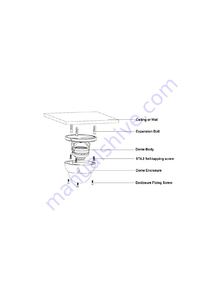
See Figure 3-1 for the installation steps.  


Figure 3-1  


Step 1 Take out the installation position map from the accessories bag, stick it on the ceiling or 

wall according to the location of cable exit. Dig holes on the installation surface according to 

the position map, take out expansion bolts from the accessories bag and put them into the 

installation holes and fix them.   


Step 2 Unscrew the three locking screws by inner hex wrench and take off the dome cover.   


Step 3 Adjust the location of dome pedestal according to the client

’s requirement of top cable 

exit or side cable exit. Pull the cable through the side cable exit which is on the installation 

surface and pedestal (please skip this step if it is top cable exit), aim the fixing holes of the 

screws on the dome pedestal to the fixing holes of expansion bolts on the installation surface, 

Summary of Contents for HAC-HDBW SERIES

Page 1: ...HDCVI IR Vandal proof Dome Camera User s Manual Version 1 0 0...

Page 2: ...Contents 1 General Introduction 1 1 1 Overview 1 1 2 Features 1 1 3 Applicable Models 1 2 Device Framework 2 3 Installation 6 4 Menu 8 4 1 HDCVI Series DVR Settings 8 4 2 Menu Operation 8 Appendix Mai...

Page 3: ...r responsibility for all the fires or electrical shock caused by improper handling or installation We are not liable for any problems caused by unauthorized modification or attempted repair 2 Environm...

Page 4: ...sh or hair dries to remove it gently Stained with grease or fingerprint Use soft cloth to wipe the water drop or oil gently to make it dry then use oil free cotton cloth or paper soaked with alcohol o...

Page 5: ...ut any loss The distance is over 300m High speed long distance real time transmission Support HDCVI HD video output Support ICR switch to realize surveillance both in the daytime and at night Support...

Page 6: ...r the dimension of HAC HDBWXXXXR Figure 2 1 See Figure 2 2 for the structure components of HAC HDBWXXXXR Figure 2 2 HAC HDBWXXXXE See Figure 2 3 for the dimension of HAC HDBWXXXXE Figure 2 3 See Figur...

Page 7: ...C HDBWXXXXE Z See Figure 2 5 for the dimension of HAC HDBWXXXXE Z Figure 2 5 See Figure 2 6 for the structure components of HAC HDBWXXXXE Z Figure 2 6 HAC HDBWXXXXF See Figure 2 7 for the dimension of...

Page 8: ...4 Figure 2 7 See Figure 2 8 for the structure components of HAC HDBWXXXXF Figure 2 8 See Figure 2 9 for the cable sequence of aviation port Figure 2 9...

Page 9: ...5 See Figure 2 10 for the structure components of HAC HDBWXXXXFP N Figure 2 10 Note There are two kinds of cable for HAC HDBWXXXXF please refer to the actual product for more details...

Page 10: ...ay result in injury After remove electrostatic attraction film don t touch dome enclosure in case it may leave stain See Figure 3 1 for the installation steps Figure 3 1 Step 1 Take out the installati...

Page 11: ...y Step 5 Adjust lens angle to a proper monitoring location after displaying image on the back end encoding device and adjust focal length of the lens to make image clear Step 6 Fix the dome enclosure...

Page 12: ...n Menu Setting System PTZ you need to select the channel number for access and set control mode as HDCVI and the protocol as DH SD1 Click Save button to save current setup See Figure 4 1 Figure 4 1 4...

Page 13: ...confirm Open menu Select menu item Select menu value Adjust lens zoom and auto trigger focus Note Thesse buttons are only applied for motorized vari focal camera Adjust lens focal length Auto focus u...

Page 14: ...ace to go to the 2nd menu Click Return button to go back to the previous menu interface Note The operation interface above is the example of HCVRHG AF series different rear end devices have different...

Page 15: ...oth and wipe several times if it is not clean enough Camera Body Maintenance Use a soft dry cloth to clean the camera body when it is dirty in case the dirt is hard to remove use a clean dry cloth soa...

Page 16: ...here are subject to change without prior written notice All trademarks and registered trademarks mentioned are the properties of their respective owners If there is any uncertainty or controversy plea...

Reviews: