background image

Specificatii tehnice

53

RO

3. 

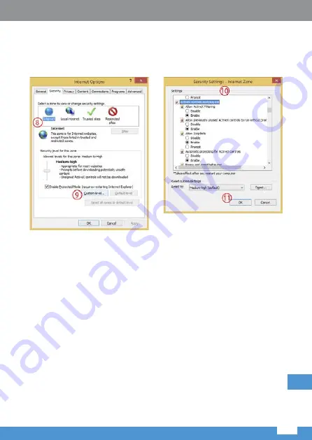
Apoi, mergeți la “Internet” > “Custom level”  și activați opțiunile în “ActiveX 

controls and plug-ins” (așa cum este arătat mai jos – vezi punctul 10). 

Apoi apăsați OK de două ori pentru a confirma.

4. 

Restartați  browser-ul  Internet  Explorer.  Odată  ce  reglarea  setărilor 

este  completă,  introduceți  adresa  IP  a  camerei  în  bara  de  adrese 

a  browserului  web  și  completați  instalarea  automată  a  plugin-urilor 

conform instrucțiunilor.

Summary of Contents for EZ-IP BULLET

Page 1: ...EZ IP BULLET NETWORK CAMERA QUICK START GUIDE Version 1 0 2 Dahua Vision Technology Co LTD EN PL RO DE...

Page 2: ......

Page 3: ...eten oder gedr ckt wird insbesondere Stecker Steckdose und Anschluss die aus dem Ger t herausragen Wir bernehmen keine Haftung oder Verantwortung f r Br nde oder Stromschl ge die durch unsachgem e Han...

Page 4: ...erursacht wurden Sie k nnen den Staub mit einer Luftpistole entfernen wenn die Abdeckung mit Staub verschmutzt ist Warnungen Sch tzen Sie das Ger t vor unbefugtem Zugang durch starke Passw rter und re...

Page 5: ...sich an Ihren lokalen Servicetechniker um weitere Informationen zu erhalten Das Unternehmen haftet nicht f r Sch den die durch den Betrieb verursacht werden der nicht der Bedienungsanleitung entsprich...

Page 6: ...ung 1 2 SN Anschluss Name Stecker Funktionsbeschreibung 1 LAN Netzwerkanschluss Ethernet Stecker Verbindung zu einem Standard Ethernet Kabel Hinweis Kamera ben tigt PoE 802 3 af Stromversorgung 2 DC 1...

Page 7: ...die Montageoberfl che Schritt 2 Stecken die D bel hinein und sichern diese fest Schritt 3 F hren Sie das Kabel aus dem Kabelausgangsloch des Ger tes Sie k nnen untere oder seitliche Verkablung w hlen...

Page 8: ...Bedienungsanleitung 8 Seitliche Verkabelung Das Kabel wird vom Ausgang des Kamerageh uses verlegt Schritt 4 Befestigen Sie die Kamera mit Hilfe der Schrauben Abbildung 2 2 Abbildung 2 3 DE...

Page 9: ...Bedienungsanleitung 9 DE Wandmontage Mastmontage Deckenmontage Eckmontage Abbildung 2 4 3 Installation Type Abbildung 2 5 Abbildung 2 6 Abbildung 2 7...

Page 10: ...igt Schritt 1 Ziehen Sie das Netzwerkkabel nacheinander durch die wasserdichte BefestigungsabdeckungunddenwasserdichtenStecker haltenSiediekonvexe Mutter nach au en und befestigen den Gummiring am Net...

Page 11: ...rschraube anzuziehen und drehen den Einstellring fest 3 Netzwerkkonfiguration Sie k nnen das Ger t initialisieren und die IP Adresse ber die WEB Benutzeroberfl che ndern Weitere Informationen finden S...

Page 12: ...mera IP Addresse in die Adressleiste ein und dr cken Enter Bitte benutzen Sie die Benutzeroberfl che gem den Anweisungen am Bildschirm wenn der Softwarelizenzvertrag und Online Aktualisierung angezeig...

Page 13: ...IP Kamera hinzu Klick Hinzuf gen danach Schlie en 2 Gehen Sie erneut zu Werkzeuge Extras Links ALT X Internet Optionen Sicherheit Vertrauensw rdige Sites Sites Geben Sie die IP Adresse der IP Kamera...

Page 14: ...nd Plug Ins Siehe Abbildung unten Punkt 10 Dr cken Sie zweimal OK zum best tigen 4 Starten Sie den Internet Explorer Browser neu Wenn die Einstellungen abgeschlossen sind geben Sie die IP Adresse der...

Page 15: ...r menschlichen Gesundheit nicht durch unkontrollierte M llbeseitigung zu schaden Recyceln Sie das Ger t um die nachhaltige Wiederverwertung von stofflichen Ressourcen zu f rdern Private Nutzer sollten...

Page 16: ...for all the fires or electrical shock caused by improper handling or installation Environment Do not aim the device at strong light to focus such as lamp light and sun light otherwise it might cause...

Page 17: ...should not be exposed to laser beam radiation in an environment where a laser beam device is used Do not provide two or more power supply sources for the device simultaneously otherwise it might damag...

Page 18: ...ation please open the package and check all the components are included Contact your local retailer as soon as possible if something is broken in your package Accessory Name Amount Network Camera Unit...

Page 19: ...dimension Figure 1 2 SN Port Port name Connector Function description 1 LAN Network port Ethernet port Connect to standard Ethernet cable Note Camera requires PoE 802 3 af power supply 2 DC 12V Power...

Page 20: ...urface Step 2 Take out expansion bolts and insert them into the mounting holes and lock them firmly Step 3 Bottom cabling It is to lead out cable from mounting surface directly which can effectively p...

Page 21: ...Owner s manual 21 EN Figure 2 2 Figure 2 3 Side cabling It is to lead out cable from housing of the camera Step 4 Use the screws to mount the camera...

Page 22: ...Owner s manual 22 EN Ceiling mounted Pole mounted Wall mounted Corner mounted Figure 2 4 Figure 2 6 Figure 2 5 Figure 2 7 3 Installation Type...

Page 23: ...and it is used outdoors The installation of waterproof connector is shown in Figure 2 8 Step 1 Pull the network cable through waterproof fastening cover and waterproof connector successively keep the...

Page 24: ...nitialize the device and modify IP address via WEB interface Please refer to the WEB Operation Manual in the disk for more details Step 3 Lay the fastening rubber ring onto the cable between waterproo...

Page 25: ...er enter the camera IP address into the address bar and then press Enter button Please operate according to the interface prompt if the interface displays guide of Software License Agreement and Onlin...

Page 26: ...ability view settings and add camera s IP address click Add then Close 2 Go to Tools left ALT X again Internet options Security Trusted sites Sites Input camera s IP address into Add this website to t...

Page 27: ...ontrols and plug ins as shown below see point 10 Then press OK twice to confirm 4 Restart the Internet Explorer browser Once the settings adjustment is finished input camera s IP address into web brow...

Page 28: ...rom uncontrolled waste disposal please separate this from other types of wastes and recycle it responsibly to promote the sustainable reuse of material resources Household users should contact either...

Page 29: ...u nadepni cia lub przygniecenia przez inne przedmioty Nale y zwr ci szczeg ln uwag na miejsca po cze wtyczki oraz miejsce wyj cia przewodu z urz dzenia Producent nie ponosi odpowiedzialno ci za obra e...

Page 30: ...wo ciach fizycznych czuciowych lub umys owych a tak e te kt re nie posiadaj do wiadczenia i nie s zaznajomionezesprz tem je elizapewnionyzostanienadz rlubinstrukta odno nie u ytkowania sprz tu w bezpi...

Page 31: ...wa z obs ug klienta w celu uzyskania informacji na temat najnowszych zalece i dodatkowej dokumentacji Nale y odwiedzi stron internetow www lechpol eu lub skontaktowa si z centrum serwisowym aby uzyska...

Page 32: ...abel Ethernet Wskaz wka Kamera wymaga zasilania PoE 802 3 af 2 DC 12V Gniazdo zasilania Gniazdo zasilania Wej cie 12 V DC Uwaga W przypadku pod czenia zasilania niezgodnego z wymaganiami urz dzenia ur...

Page 33: ...co najmniej 3 krotno wagi uchwytu i kamery Krok 1 Nale y wywierci otwory Krok 2 Umie ci w nich ko ki rozporowe Krok 3 Przeprowadzi przew d z urz dzenia do em lub bokiem Przeprowadzenie przewod w do e...

Page 34: ...Instrukcja obs ugi 34 Rys 2 2 Przeprowadzenie bokiem nale y przeprowadzi przew d przez obudow boczn kamery Krok 4 Przymocowa kamer za pomoc wkr t w Rys 2 3 PL...

Page 35: ...Instrukcja obs ugi 35 PL Do sufitu Rys 2 4 Do ciany Rys 2 5 Do s upa Rys 2 6 Rys 2 7 Naro na 3 Sposoby instalacji...

Page 36: ...porn z czk Schemat monta u wodoodpornej z czki przedstawiony jest na rys 2 8 Rys 2 8 Krok 1 Nale y przeci gn kabel sieciowy przez os on wodoodpornej z czki a nast pnie przez z czk Wypustka musi znajdo...

Page 37: ...ci ruby 3 Konfiguracja sieci U ytkownik mo e skonfigurowa urz dzenie i zmieni adres IP w interfejsie u ytkownika przez przegl dark Wi cej informacji dost pnych jest w pe nej instrukcji obs ugi Krok 3...

Page 38: ...tkownika przez przegl dark Krok 1 Nale y otworzy przegl dark Internet Explorer wpisa adres IP kamery w pasku adresu i nacisn przycisk Enter na klawiaturze Nale y post powa zgodnie z krokami wy wietlan...

Page 39: ...AJ nast pnie ZAMKNIJ 2 Nast pnie ponownie wybra opcj NARZ DZIA lewy ALT X przej do Opcje internetowe i wybra zak adk Zabezpieczenia gdzie nale y zaznaczy Zaufane witryny i klikn przycisk Witryny W pol...

Page 40: ...zamy opcje jak na ilustracji poni ej punkt 10 po czym nale y zatwierdzi przyciskiem OK w oknie Ustawienia zabezpiecze i ponownie OK w oknie OPCJE INTERNETOWE 4 Nast pnie zrestartowa przegl dark Intern...

Page 41: ...nnego typu odpad w oraz odpowiedzialny recykling w celu promowania ponownego u ycia zasob w materialnych jako sta ej praktyki W celu uzyskania informacji na temat miejsca i sposobu bezpiecznego dla ro...

Page 42: ...zei sau leg turii care iese din dispozitiv Nu ne asum m nicio responsabilitate sau r spundere pentru incendiile sau ocurile electrice cauzate de manipularea sau instalarea necorespunz toare Mediul nco...

Page 43: ...ita furtul de date Utiliza i componente sau accesorii standard furnizate de produc tor i asigura i v c dispozitivul este instalat i ntre inut de ingineri specializa i Suprafa a senzorului de imagine n...

Page 44: ...i explica ia noastr final Not Consulta i CD ul pentru mai multe detalii nainte de instalare deschide i ambalajul i verifica i dac ave i toate componentele Contacta i furnizorul local c t mai repede da...

Page 45: ...necesit alimentare PoE 802 3 af 2 DC 12V Port intrare alimentare Port alimentare Intrare DC 12V Aten ie Poate cauza deteriorarea produsului dac acesta nu este alimentat conform descrierii de pe etiche...

Page 46: ...n suprafa a de montare Pasul 2 Scoate i diblurile i introduce i le n orificiile pentru montare i fixa i le bine Pasul 3 Scoate i cablul prin orificiul de ie ire al dispozitivului pute i selecta cablar...

Page 47: ...Specificatii tehnice 47 RO Cablarea lateral Cablul este trece prin partea lateral a suportului camerei Pasul 4 Utiliza i uruburile pentru a monta camera Figure 2 2 Figure 2 3...

Page 48: ...Specificatii tehnice 48 RO La plafon La perete La pol Col 3 Tipuri de instalare Figure 2 4 Figure 2 6 Figure 2 7 Figure 2 5...

Page 49: ...zitivul i aparatul este utilizat n exterior Instalarea conectorului rezistent la ap este afi at n Figure 2 8 Pasul 1 Trage i cablul de re ea prin capacul de fixare rezistent la ap i succesiv prin cone...

Page 50: ...3 Configurare re ea Pute i ini ializa dispozitivul i modifica adresa IP prin interfa a WEB Consulta i Manual de func ionare WEB de pe CD pentru mai multe detalii Pasul 3 Pune i inelul de cauciuc pent...

Page 51: ...ozitivului n bara de adrese i ap sa i Enter V rug m s ac iona i conform solicit rii interfe ei dac aceast afi eaz ghidul Acordul de licen software i Actualizare Online IMPORTANT utilizarea altui brows...

Page 52: ...settings i ad uga i adresa IP a camerei face i click pe Add apoi Close 2 Merge i la Tools alt ST NGA X din nou Internet options Security Trusted sites Sites Introduce i adresa IP a camerei n spa iul...

Page 53: ...ins a a cum este ar tat mai jos vezi punctul 10 Apoi ap sa i OK de dou ori pentru a confirma 4 Restarta i browser ul Internet Explorer Odat ce reglarea set rilor este complet introduce i adresa IP a...

Page 54: ...urilor v rug m s separa i acest produs de alte tipuri de reziduuri si s l reciclati in mod responsabil pentru a promova refolosirea resurselor materiale Utilizatorii casnici sunt rugati s ia legatura...

Page 55: ......

Page 56: ......

Reviews: