


-55-
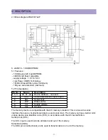
IC DESCRIPTION
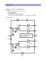
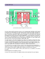
7 FUNCTIONAL DESCRIPTION OF VIDEO PROCESSOR
7.1 Vision IF amplifier
The vision IF amplifier can demodulate signals with positive and megative modulation. The PLL
demodulator is completely alignment-free.
The VCO of the PLL circuit is internal and the grequency is fixed to the required value by using
the clock ftequency of the TCG u-Controller as a reference. The setting of the various
frequencies (e.g. 38, 38.9, 45.75 and 58.75MHz) can be made via the control bits IFA-IFC in
subaddress 2FH. Because of the internal VCO the IF circuit has a high immunity to EMC
interferences.
The output of the AFC detector can be read from output byte o4H and has a resolution of
7bit(25kHz per step). By means of this information a fast tuning algorithm can be designed.
The IC contains a group delay correction circuit which can be switched between the BG and a
uncompensated group delay response characteristic. This hasthe advantage that in multi-
standard receivers no compromise has to be made for the choice of the SAW filter. This group
delay corection is realised for the demodulated CVBS output signal. The IC contains in addition
a sound trap circuit with a switchable centre frequency.
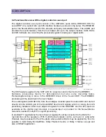
7.2 QSS sound circuit
The sound IF amplifier is similar to the vision IF amplifier and has an external AGC decoupling
capacitor.
The singler eference QSS mixer is realised by a multiplier. In this multiplier the SIF signal is
converted to the intercarrier frequency by mixing it with the regenerated picture carrier from the
VCO. The mixer output signal is supplied to the output via a high-pass filter for attenuation of
the residual video signals. With this system a high performance hi-fi stereo sound processing
can be achieved.
The AM sound demodulator is realised by a multiplier.The modulated sound IF signal is
multiplied in
phase with the limited SIF signal. The demodulator output signal is supplied to the output via a
low-pass filter for attenuation of the carrier harmonics.
Switching between the QSS output and AM output is made by means of the AM bit in
subaddress 33H.
7.3 FM demodulator
The FM demodulator is realised as narrow-band PLL with internal loop filter, which provides the
necessary selectivity without using an external band-pass filter. To obtain a good selectivity a
linear phase detector and a constant input signal amplitude are required. For this reason the
intercarrier signal is internally supplied to the demodulator via a gain controlled amplifier and
AGC circuit. To improve the selectivity an internal bandpass filter is connected in front of the
PLL circuit.
The nominal frequency of the demodulator is tuned to the required frequency (4.5/5.5/6.0/6.5
MHz) by means of a calibration circuit which uses the clock frequency of the TCG(1)-Controller
as a reference. It is also possible to frequencies of 4.72 and 5.74Mhz so that a second sound
channel can be demodulated. In the latter application an external bandpass filter has to be
Summary of Contents for DTU-29M5ME
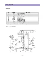
Page 5: ...4 3 CIRCUIT BLOCK DIAGRAM...
Page 16: ...15 5 CM 500 F TYPICAL SERVICE DATA...
Page 26: ...25...
Page 27: ...26...
Page 28: ...27...
Page 29: ...28...
Page 30: ...29 DTU 29M5...
Page 31: ...30 DTU 29M6...
Page 32: ...31 DTU 29M7...
Page 33: ...32 DTU 29U1...
Page 35: ...34 CM 500F 4858311110 DTU 29U8 4859645360 12W 8 SP 58126F DTU 29U8...
Page 36: ...35 DTU 29F1 CM 500F 4859845360 CPT A68AKY13X CM 500F CM 500F DTU 29F1...
Page 37: ...36 DTU 29F2 CM 500F 4859845360 CPT A68AKY13X CM 500F DTU 29F2...
Page 38: ...37 DTU 29F3 CM 500F 4859845360 CPT A68AKY13X CM 500F CM 500F DTU 29F3...
Page 40: ...39 IC DESCRIPTION...