

-49-
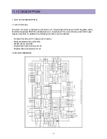
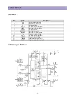
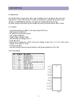
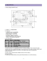
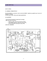
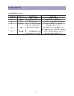
IC DESCRIPTION
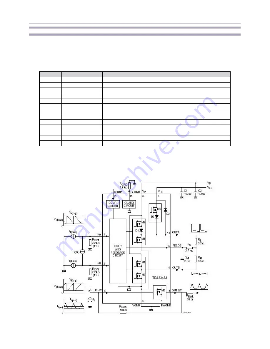
Pin
Symbol
Description
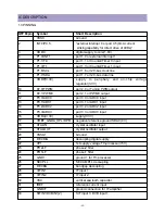
1
INA
Positeve vertical input
2
INB
Negative vertical input
3
V
P
Supply voltage
4
OUTB
Vertical output voltage B
5
INEW
East-west input voltage
6
VGND
Vertical ground
7
EWGND
East-west ground
8
OUTEW
East-west output voltage
9
V
FB
Flyback supply voltage
10
OUTA
Vertical output voltage A
11
GUARD
Guard output voltage
12
FEEDB
Input measuring resistor
13
COMP
Input compensation current
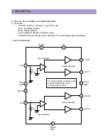
3.2 PINNING
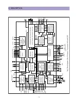
3.3 Block diagram TDA83583
Summary of Contents for DTU-29M5ME
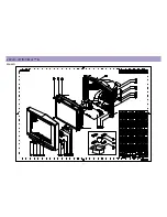
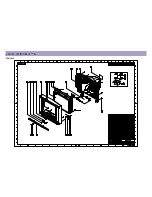
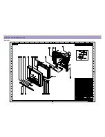
Page 5: ...4 3 CIRCUIT BLOCK DIAGRAM...
Page 16: ...15 5 CM 500 F TYPICAL SERVICE DATA...
Page 26: ...25...
Page 27: ...26...
Page 28: ...27...
Page 29: ...28...
Page 30: ...29 DTU 29M5...
Page 31: ...30 DTU 29M6...
Page 32: ...31 DTU 29M7...
Page 33: ...32 DTU 29U1...
Page 35: ...34 CM 500F 4858311110 DTU 29U8 4859645360 12W 8 SP 58126F DTU 29U8...
Page 36: ...35 DTU 29F1 CM 500F 4859845360 CPT A68AKY13X CM 500F CM 500F DTU 29F1...
Page 37: ...36 DTU 29F2 CM 500F 4859845360 CPT A68AKY13X CM 500F DTU 29F2...
Page 38: ...37 DTU 29F3 CM 500F 4859845360 CPT A68AKY13X CM 500F CM 500F DTU 29F3...
Page 40: ...39 IC DESCRIPTION...