


- 11 -
APPENDIX
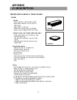
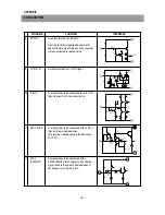
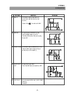
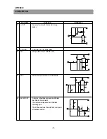
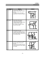
IC DESCRIPTION
PIN NAME
FUNCTION
INTERFACE
41
EW OUT
An output terminal for E-W out.
42
Y/C VCC
An Vcc terminal for Y/C circuit.
Supply 5V.
43
C-IN
An input terminal for chroma signal.
(standard burst amplitude level 286mVp-p)
The Iow/High impedance status of this pin can
be read by bus to detect if S port is connceted
or not.
44
Cr IN
Input terminals for Cb/Cr signals.
45
Cb IN
This terminal is clamped by charging/
discharging the coupling capacitors
It is recommended that input impedance is
kept at or below 100 .
B.B.TINT (-/+ 12deg) / Sub color control are
available for Cb/Cr input signals.
46
VSM OUT
The output terminal for veracity scanning
modulation (VSM).
The IIC Bus controls phase and Gain of VSM.
41
31
40
42
19
44
45
42
19
46
42
14
Summary of Contents for DTD-29U8ME
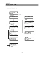
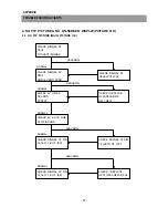
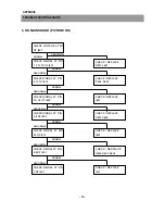
Page 5: ...4 CIRCUIT BLOCK DIAGRAM...
Page 12: ...SCHEMATIC DIAGRAM 11...
Page 13: ...PRINTED CIRCUIT BOARD PCB MAIN 12...
Page 14: ...13 PRINTED CIRCUIT BOARD...
Page 15: ...14 PRINTED CIRCUIT BOARD...
Page 17: ...16 PRINTED CIRCUIT BOARD...
Page 18: ...17 PRINTED CIRCUIT BOARD...
Page 19: ......


