


- 7 -
APPENDIX
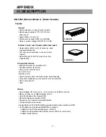
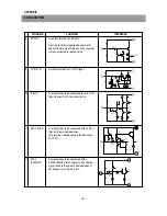
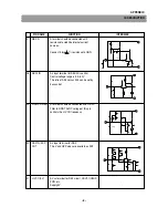
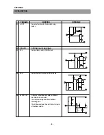
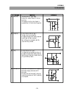
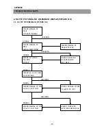
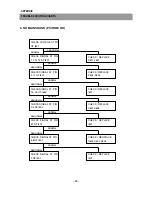
IC DESCRIPTION
PIN NAME
FUNCTION
INTERFACE
23
IK IN
An input terminal to sense AKB cathode
current.
Connect this terminals to GND if the AKB
system is not being used.
24
V RAMP
A terminal should be connected wiht a
capacitor to generate the V.Ramp signal.
The V.Ramp amplitude is kept constant by
the V.AGC.
25
V NFB
An input terminal for the V saw-tooth signal
feedback.
If the DC voltage on this pin is less than 1.7V,
it blanks RGB output for V guard.
26
V OUT
An output terminal for the vertical driving
pulses.
19
23
12
31
24
33
31
25
33
12.5k
2V
31
26
33
Summary of Contents for DTD-29U8ME
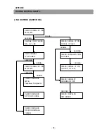
Page 5: ...4 CIRCUIT BLOCK DIAGRAM...
Page 12: ...SCHEMATIC DIAGRAM 11...
Page 13: ...PRINTED CIRCUIT BOARD PCB MAIN 12...
Page 14: ...13 PRINTED CIRCUIT BOARD...
Page 15: ...14 PRINTED CIRCUIT BOARD...
Page 17: ...16 PRINTED CIRCUIT BOARD...
Page 18: ...17 PRINTED CIRCUIT BOARD...
Page 19: ......


