- 4 -
APPENDIX
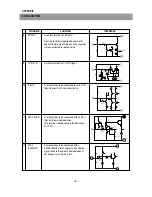
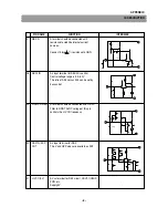
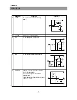
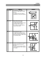
PIN NAME
FUNCTION
INTERFACE
1
IF VCC
A Vcc terminal for the IF circuit.
Supply 5V.
2
RIPPLE
A terminal should be connected to an internal
FILTER
bias filler. Put a capacilor.
3
SIF OUT
An output terminal for a 2’nd SIF signal, that
is mixed down by a regenerated carrier.
The SIF frequencies are able to convert into
only 6.5MHz, in order to eliminate SIF BPFs
to single 6.5MHz.
4
AUDIO OUT
An output terminal for audio signal.
FM Det.signal, inputted to pin53, is output.
An internal audio attenator controls the output
levels.
5
IF GND
The GND terminal for IF circuit.
6
IF IN
Input terminals for IF signals. Pin 6 and 7 are
7
IF IN
the both input poles of a differential amplifier.
The normal input level is 90dB( V )( Pin6-7),
input impedance is 1.5 k ohms.
TERMINAL INTERFACE
-
-
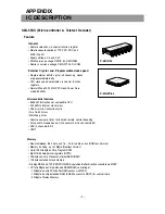
IC DESCRIPTION
Summary of Contents for DTD-29U8ME
Page 5: ...4 CIRCUIT BLOCK DIAGRAM...
Page 12: ...SCHEMATIC DIAGRAM 11...
Page 13: ...PRINTED CIRCUIT BOARD PCB MAIN 12...
Page 14: ...13 PRINTED CIRCUIT BOARD...
Page 15: ...14 PRINTED CIRCUIT BOARD...
Page 17: ...16 PRINTED CIRCUIT BOARD...
Page 18: ...17 PRINTED CIRCUIT BOARD...
Page 19: ......


