background image

8

2.  To install the bracket, place it against the wall in the mounting 

location. Using a drill with a 1/8” diameter drill bit, drill four 

(4) 1 5/8” deep pilot holes perpendicular to the screw seating 

surfaces shown below. Attach the bracket to the wall as 

shown with the four (4) included #12 x 1 3/4 screws.

Installing the Anti-Tip Bracket on the Wall

1.  Determine the suitability of wall mounting the anti-tip bracket. 

To use the wall mount option, the range front panel (excluding 

the bull nose) must not be more than 27” (68.6 cm) from the 

wall and the bracket screws must be able to thread into the 

base plate inside the wall behind. The notches on the sides 

of the bracket indicated the minimum required height of the 

base plate inside the wall and that any floor covering is not 

too thick for proper screw thread engagement.

To determine if the base plate is high enough:

◊ 

Determine the location of the range center line and front 

panel when the range is in its final position based on the 

product dimensions on page 5 and the actual cabinet/

cutout dimensions used for the installation.

◊ 

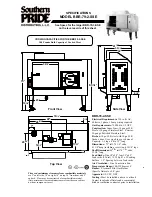
Determine and mark the required position of the anti-tip 

bracket, based on the diagram above. Push the bracket 

up against the wall in the mounting location.

◊ 

Using a pencil, make a dot next to the notches on both 

sides of the bracket. Determine if the base plate is as 

high at the notches by drilling test holes into the wall at 

both dots with a 1/16” drill bit. Drill just deep enough to 

see if the bit contacts the base plate. If the bit contacts 

the base plate the location will support wall installation of 

the anti-tip bracket. If you do not contact the base plate, 

the wall mounting method may not be used and the floor 

mounting method must be suitable, or the wall must be 

modified so that the base plate is above the notches.

Installation Instructions

CL

CL

Bracket

center line

Range front

panel*

#12 x 1 3/4” 

screw, 4 places

This hole lines up with

bracket center line

Back wall

Range

center line

Wall

Anti-tip

bracket

Base 

plate

Drywall

Notch

Top View - Location of Wall Mounted Anti-Tip 

Bracket

C

ANTI-TIP BRACKET PLACEMENT

Dimension

RNRP36G

RNRP48G

C

11 7/8” (30.2 cm)

2 1/2” (6.4 cm)

* Excludes bull nose (see page 4)

Summary of Contents for Renaissance RNRP36G

Page 1: ...structions Renaissance Gas Range Part No 108531 Rev B THIS APPLIANCE HAS BEEN TESTED IN ACCORDANCE WITH THE LATEST EDITIONS OF ANSI Z21 1 UL858 AND UL60730 1 STANDARDS FOR HOUSEHOLD APPLIANCES Models RNRP36GS RNRP48GS ...

Page 2: ...the Range After Service 13 Installation Checklist 13 Customer Service Information If you have questions or problems with installation contact your Dacor dealer or the Dacor Customer Service Team For repairs to Dacor appliances under warranty call the Dacor Distinctive Service line Whenever you call have the model and serial number of the appliance ready The model and serial number label is located...

Page 3: ...is appliance as a space heater to heat or warm the room Doing so may result in carbon monoxide poisoning and overheating of the appliance WARNING NEVER cover any slots holes or passages on the inside or outside of the range or cover an entire rack with materials such as aluminum foil Doing so blocks air flow through the oven and may cause carbon monoxide poisoning Aluminum foil linings may also tr...

Page 4: ...ended in the area around the range Do not allow children to play with the controls pull on the handle s or touch other parts of the range Do not store items of interest to children on top of or above the range Children could be burned or injured while climbing on the appliance Do not attempt to use this appliance in the event of a power failure Clean the cooktop thoroughly before operating it for ...

Page 5: ...quirements The installation of this appliance must conform with local codes or in the absence of local codes with the National Fuel Gas Code ANSI Z223 1 NFPA 54 Be certain that the appliance being installed is correct for the gas service provided natural gas or LP gas Also if operating the range at an altitude above 4000 ft 1219 m make sure it is equipped for high altitude operation Refer to the r...

Page 6: ... 26 66 0 cm 24 61 0 cm 1 1 4 3 2 cm to 1 1 16 2 7 cm to cooking surface top of grates from top of trim Finished side panel X 24 61 0 cm Cabinet face lines up with back of control panel Product tolerances 1 16 1 6 mm Product Dimensions The backguard is available in two heights 3 inches standard and 9 inches optional Width RNRP36G 35 7 8 91 1 cm RNRP48G 47 7 8 121 6 cm View of Range Installed Side V...

Page 7: ...etween the gas inlet and the range for the purpose of turning on or shutting off gas to the appliance The installation must allow for the following Access to the gas shut off valve when the unit is installed Access to the electrical outlet when the range is in place The gas supply piping and shut off valve and the electrical outlet must be located so they do not interfere with the range when it is...

Page 8: ...l the optional 9 inch backguard before making the range gas and electrical connections Install it according the installation instructions included with the backguard kit Approved backguard kits Model Description APB36D9 9 inch high backguard for range model RNRP36G APB48D9 9 inch high backguard for range model RNRP48G Install the Anti Tip Bracket and Foot Locate the anti tip bracket included in th...

Page 9: ...w threaded into wood slab for wood is 3 8 1 cm and 5 8 1 6 cm for concrete See SCREW SIZE TABLE to select the correct screw size Attaching the bracket to a concrete floor Drill four 4 3 8 diameter countersink holes through any existing floor covering down to the concrete slab below Drill the 4 holes for the anchors 1 1 4 3 2 cm deep into the concrete slab using a 3 16 masonry bit This hole length ...

Page 10: ...nsions on page 5 and the actual cabinet cutout dimensions used for the installation Determine and mark the required position of the anti tip bracket based on the diagram above Push the bracket up against the wall in the mounting location Using a pencil make a dot next to the notches on both sides of the bracket Determine if the base plate is as high at the notches by drilling test holes into the w...

Page 11: ...ected from the gas supply piping during any pressure testing exceeding 1 2 psi 3 5 kPa The range must be isolated from the gas supply piping by closing the shut off valve during any pressure testing at or below 1 2 psi 3 5 kPa Check all gas lines for leaks as instructed to avoid a fire or explosion hazard Do not use a flame to check for leaks NOTE The gas pressure regulator is pre set at the facto...

Page 12: ...he notch on the bottom of each hinge rests on top of the lower lip of each hinge receptacle before attempting to open the oven door Rotate the hinge locks toward the front of the range immediately after installation of the door 1 Grasp the oven door on opposite sides and hold it at a 15 angle from the front of the oven Slide the hinges into the hinge openings resting the bottom of the hinge arms o...

Page 13: ...e 3 different types of knobs supplied with the range The oven knob s has have the word BROIL on them The knobs for the middle burners have the words MAX GRIDDLE on them 1 Put the oven knob s A on the oven valve shaft s as shown 2 Put the knobs with the words MAX GRIDDLE on them B onto the center burner valve shafts as shown 3 Put the remaining knobs C on the outer valve shafts as shown Icons on Ce...

Page 14: ... pieces are properly seated Gently set the grates on top of the spill tray Put the legs of each grate inside the corresponding dimples SimmerSear Burner Installation Standard Burner Installation STEP 1 Install burner head Put locating tab in keyed hole STEP 1 Put burner ring on top of head STEP 2 Install burner ring Line up ring tabs with head slots STEP 2 Turn ring until it drops into place STEP ...

Page 15: ...the IR burner on the ceiling of the oven should ignite and begin to give off heat 12 Turn the oven knob to the OFF position On model RNRP48G test both ovens If the range does not operate properly follow these troubleshooting steps 1 Verify that power and gas are supplied to the range 2 Check the electrical connections and gas supply to ensure that the installation has been completed correctly 3 Re...

Page 16: ...Dacor 14425 Clark Avenue City of Industry CA 91745 Phone 800 793 0093 Fax 626 403 3130 www dacor com ...

Reviews: