10
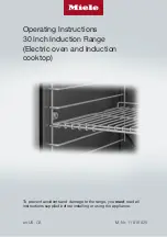
Installation Instructions
Removing the Oven Door
WARNING
•
Do not attempt to disengage the hinge catches with the
door(s) removed from the range. The hinge springs could
release causing personal injury.
•
Do not lift or carry the oven door(s) by the handle.
NOTE
: When installing a backguard, always install it before sliding
the range into place. See page 7.
To make the range easier to move, remove the door(s) to reduce
weight.
1. Open the door until its lying completely open and flat.
2. Use a pair of needle nose pliers and a flat blade screwdriver
to rotate the catch over the retaining arm on each hinge (see
Oven Door Hinge
)
3. Close the oven door three-quarters shut (see below).
4. Grasp each side of the door, just below the handle, with both
hands.
5. In a single motion, pull the door away from the oven while
continuing to lift up and out.
Door Closed Three-Quarters and Hand Placement
Catch
Retaining Arm
Connecting the Gas
WARNING
• Make sure the gas supply valve is off and that the power
cord to the range is disconnected prior to connecting the
gas line.
• Do not apply excessive pressure when tightening gas
connections and fittings.
• Do not use Teflon tape or plumber’s putty on gas flex line
connections.
• For LP installations, the LP gas tank must have its own
high pressure regulator. This is in addition to the pressure
regulator provided with the range.
• The maximum gas supply pressure to the regulator must
never exceed 1/2 pound per square inch (psi) or 3.5 kPa.
• The range and shut-off valve must be disconnected from the
gas supply piping during any pressure testing exceeding 1/2
psi (3.5 kPa).
• The range must be isolated from the gas supply piping by
closing the shut-off valve during any pressure testing at or
below 1/2 psi (3.5 kPa).
• Check all gas lines for leaks as instructed to avoid a fire or
explosion hazard. Do not use a flame to check for leaks.
NOTE:
The gas pressure regulator is pre-set at the factory for the
type of gas intended for use with the appliance.
To verify that the appliance is compatible with the type of gas
available, check the range rating label (see inside cover for
location). Ranges intended for use with LP gas will have “LP” as a
part of the model number. Consult your dealer if the range is not
compatible with the type of gas being supplied.
Before Sliding the Range into Position:
1. Make sure the gas supply valve is OFF, and power to the
range is OFF.
2. Connect a flexible gas supply line to the gas shut-off valve.
This gas line needs to be long enough to allow the range
enough distance to be pulled out for service.
3. Slide the gas line up through the range’s access holes in the
back of chassis and up to the regulator. Move the wires tht
are inside the access holes to prevent them from catching on
the gas line as you maneuver the gas line.
4. Connect the gas line to the regulator.
5. Turn all cooktop control valves to OFF.
6. Turn the gas supply
ON.
7. Check all lines and
connections for
leaks using a soap
and water solution.
8. After verifying that
there are no gas
leaks, turn the
gas supply valve
connected to the
range to OFF.
Regulator
Oven Door Hinge
Flexible Gas Line
Summary of Contents for Renaissance RNRP30G
Page 18: ...16 Notes ...
Page 19: ...Notes ...