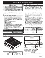
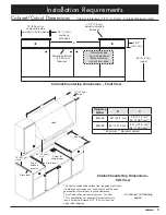
Dacor Renaissance EG486SCHNG Installation Instructions Manual Download Page 5

3

Product Dimensions

RANGETOP WIDTH (A)

EG366

35 7/8” (91.1 cm)

EG486

47 7/8” (121.6 cm)

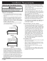
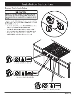
Installation Requirements

 WARNING

•  Observe all governing codes and ordinances during 

planning and installation. Contact your local building 

department for further information.

•  To prevent an electric shock hazard, the power sup-

ply must meet the specifications stated below. 

The electrical and gas supply data on this page is for refer-

ence only. If the requirements below do not agree with the 

product data label, use the data on the product data label.

Electrical Requirements

•  The electrical installation, including minimum supply 

wire size and grounding, must be done in accordance 

with National Electric Code ANSI/NFPA 70 and local 

codes and ordinances. A copy of this standard may be 

obtained from:


National Fire Protection Association 


1 Batterymarch Park  


Quincy, MA 02269-9101

•  The correct voltage, frequency and amperage must be 

supplied to the electrical outlet according to the product 

data label located on the bottom of the chassis.

•  The electrical outlet must be installed by a licensed 

electrician.

ELECTRIC CIRCUIT REQUIREMENTS

Circuit Required

Total Connected Load

120 Vac 60 Hz,  

15 Amp. (3 wire)

0.25 Amp @ 120 Vac, 60 Hz

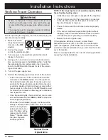
Gas Supply Requirements

•  Check your local building codes for the proper method 

of installation. In the absence of local codes, this 

appliance should be installed in accordance with the 

National Fuel Gas Code ANSI Z223.1/NFPA 54. The 

gas service must be installed by a qualified profes-

sional

•  Be certain that the rangetop being installed is cor-

rect for the gas service being provided (natural gas or 

LP gas). Also, if operating the rangetop at an altitude 

above 4000 ft. (1219 m) make sure it is equipped for 

high altitude operation. See the inside cover for more 

information.

•  An external manual shut-off valve must be installed 

between the gas inlet and the rangetop for the purpose 

of turning on or shutting off gas to the appliance.

•  The factory provided regulator shipped with the appli-

ance must be installed in the gas line that runs from the 

gas shut off valve to the rangetop gas inlet. Use only 

the regulator provided. The regulator inlet accommo-

dates a 3/4” gas supply line and is also compatible with 

a 1/2” house gas supply. The inlet to the rangetop itself 

is equipped with a 3/4” male NPT fitting.

GAS SUPPLY PRESSURE REQUIREMENTS*

Gas Type

Manifold 

Pressure

Minimum Gas 

Supply Pressure

Natural Gas

5” Water Column 6” Water Column

Propane (LP)

10” Water

Column

11” Water Column

* Maximum gas supply pressure for all models is 1/2 psi
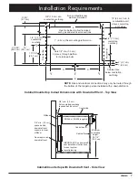
A

4” (10.2 cm)

5/8” 

(1.6 cm)

7 3/4”

 (19.7 cm)

Trim:

7/16”

 (1.1 cm)

thick

26” (66.0 cm)

1 1/2” (3.8 cm) cooking surface 

height (grate level) above 

countertop

3/4” gas inlet, connects to regulator from 

bottom or rear of unit, end is recessed 

2” (5.1 cm) from chassis bottom

27” (68.6 cm)

28” (71.1 cm)

Power cord

32” long

Product tolerances: ±1/16” (±1.6 mm) unless otherwise 

noted.

SIDE VIEW

Summary of Contents for Renaissance EG486SCHNG

Page 1: ...tallation Instructions Renaissance Rangetop Models EG366 EG486 Part No 102025 Rev T THIS APPLIANCE HAS BEEN TESTED IN ACCORDANCE WITH THE LATEST EDITION OF ANSI Z21 1 STANDARD FOR HOUSEHOLD GAS APPLIANCES ...

Page 2: ...rence and the local building inspector s use 2007 Dacor all rights reserved If You Need Help If you have questions or problems with installation contact your Dacor dealer or the Dacor Customer Service Team For repairs to Dacor appliances under warranty call the Dacor Distinctive Service line Whenever you call have the model and serial number of the appliance ready The model and serial number are p...

Page 3: ...T If you smell gas Do not use or light any appliance Do not touch any electrical switch or use any electri cal devices including the telephone in your building From a neighbor s phone immediately call the gas supplier Follow the gas supplier s instructions If you cannot contact the gas supplier call the fire department DANGER IMPORTANT Do not store or use combustible flammable or explosive vapors ...

Page 4: ...om panying it This rangetop is not intended for commer cial or laboratory use DO NOT TOUCH THE SURFACES OF THE RANGETOP OR THE SURROUNDING AREAS DURING OR IMMEDIATELY AFTER USE WARNING General Safety Precautions To reduce the risk of fire electric shock serious injury or death when using your appliance follow basic safety precau tions including the following Do not climb on any part of the applian...

Page 5: ...ce should be installed in accordance with the National Fuel Gas Code ANSI Z223 1 NFPA 54 The gas service must be installed by a qualified profes sional Be certain that the rangetop being installed is cor rect for the gas service being provided natural gas or LP gas Also if operating the rangetop at an altitude above 4000 ft 1219 m make sure it is equipped for high altitude operation See the inside...

Page 6: ...panel and cre ates a seamless look for the installation IMPORTANT When installing the rangetop into a lami nated or synthetic countertop radius the corners of the cutout to help avoid cracking Consult the countertop manufacturer s instructions for minimum corner radius reinforcement and heat protection requirements For installations with a downdraft vent install this appli ance only with the appro...

Page 7: ...otherwise noted Rangetop Model B C EG366 36 91 4 cm 36 91 4 cm 42 106 7 cm EG486 48 121 9 cm 48 121 9 cm 54 137 2 cm Minimum Recommended Continued on following pages See note 2 2 See Cabinet Countertop Dimensions Top View 3 This specification not applicable for cabinets more than a horizontal distance of 10 25 4 cm from the edge of the rangetop 1 Vertical to combustible surface from rangetop grate...

Page 8: ... D 20 3 cm X 15 2 cm if gas and electrical are routed through bottom 1 2 1 3 cm countertop overhang 1 2 5 cm thick mounting platform min Countertop Countertop 1 2 1 3 cm countertop overhang 2 5 1 cm 1 2 5 cm 11 7 16 29 1 cm 24 5 8 62 5 cm C L D D B C L C L C L Rangetop Model B Cutout Width D Hole Offset E Downdraft Vent Cutout Approved Downdraft Vent Models EG366 36 91 4 cm 16 5 8 42 2 cm 33 1 2 8...

Page 9: ...n to below to allow for raised vent gas and electrical connections Countertop Countertop 1 2 1 3 cm countertop overhang 2 5 1 cm 1 2 5 cm 11 7 16 29 1 cm 15 38 1 cm 24 5 8 62 5 cm C L D D E B C L C L C L Stiffener Cabinet face Control panel Countertop Dacor approved downdraft vent IMPORTANT See downdraft vent installation instructions for duct system layout planning EG366 or EG486 rangetop 3 8 min...

Page 10: ...wn bolts PN 83383 2 washers for hold down bolts PN 83203 Regulator NG PN 62834 LP PN 72980 Product literature 1 Model EG486 comes with 3 14 inch grates PN 700038 Model EG366 comes with 2 10 inch grates PN 700037 and 1 14 inch grate PN 700038 2 PN 100699 includes 1 burner ring and 1 burner cap 3 PN 700493 includes 1 burner ring and 1 burner cap 4 PN 100703 includes 1 burner base 1 burner ring and 1...

Page 11: ... off valve to the rangetop dur ing any gas supply piping system pressure testing equal to or less than 1 2 psi 3 5 kPa For LP gas installations the LP gas tank must have its own high pressure regulator in addition to the pressure regu lator supplied with the rangetop IMPORTANT Within the Commonwealth of Massachusetts this appliance must be installed by a licensed plumber or gas fitter 1 Attach the...

Page 12: ...he burn er components twist each piece back and forth slightly until it drops completely into place The burners will not operate properly unless all of the burner pieces are properly seated Gently set the grates on top of the spill trays Make sure that the rubber feet are positioned in the dimples On model EG366 the center grate is larger than the other two STEP 1 Install burner head Put locating ...

Page 13: ...obs supplied with the rangetop The knobs for the center burners have the words MAX GRIDDLE on them Put the knobs with the words MAX GRIDDLE on them onto the inner center burner valve shafts Put the remaining knobs on the outer valve shafts When installing the knobs align the D shaped open ing on the back of the knob with the end of the valve shaft Carefully push the knob on until it stops Icons on...

Page 14: ...ition wait for at least five minutes to allow any gas to dissipate then repeat the test Once the burner lights the control knob can be rotat ed counterclockwise from HIGH to LOW to adjust the flame height progressively When the unit is installed properly the flame will be steady It will also have a sharp blue inner cone that will vary in length pro portional to the burner size The flame will be re...

Page 15: ...nd installed according to these instructions and in accordance with all applicable codes See pages 3 and 4 Has the gas supply inlet pressure been measured to ensure that it does not exceed the maximums stated in these instructions See page 3 Is the rangetop secured using the provided hold down bolts and washers See page 8 Is the rangetop connected to the gas supply according to these instructions ...

Page 16: ...NESS O O O O O O B B B B B B B B RL BURNER IGNITOR IGNITOR RC BURNER RR BURNER IGNITOR IGNITOR FR BURNER IGNITOR FL BURNER FC BURNER IGNITOR S1 S2 S3 S4 S6 S5 B B B B BLACK WHITE FR LED HARNESS W W W W FL LED HARNESS Single Point Spark Module W W W W W Single Point Spark Module Single Point Spark Module W W Single Point Spark Module W W Single Point Spark Module FC LED HARNESS W W W W W RL LED HAR...

Page 17: ...15 Notes ...

Page 18: ...16 Notes ...

Page 19: ......

Page 20: ...Dacor 14425 Clark Avenue City of Industry CA 91745 Phone 800 793 0093 Fax 626 403 3130 www dacor com ...

Reviews: