Dacor REMP16 Installation Instructions Manual Download Page 8

6

 WARNING

If the electrical service provided does not meet the 

• 

power requirements for the hood/raised vent and the 

blower combined, do not continue with the instal-

lation. Contact a licensed electrician to correct the 

situation before continuing.
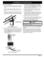
Failure to connect the wiring as specified may result 

• 

in an electric shock hazard and/or improper blower 

operation.
To avoid the risk of fire or electric shock, turn off 

• 

power at the circuit breaker panel or fuse box before 

connecting the blower to the power source.
The blower assembly is heavy. Do not attempt to lift 

• 

or move it without assistance.

Parts List

Verify Package Contents

2 1/2” wood mounting screws (8)

• 

Blower assembly

• 

Parts Required

3 conductor wiring/conduit with UL certified strain relief 

• 

on each end (length is determined by remote blower 

location).
If the blower will be mounted to a surface other than 

• 

wood, fasteners designed for the material the unit will 

be mounted to must be provided. The fasteners must 

be capable of supporting the weight of the blower (see 

weight table on page 5) and meet local codes and ordi-

nances.
Consult the hood or raised vent installation instructions 

• 

for additional part requirements.

Installation

Before installing the blower, unpack the unit and check 

1. 

for physical damage to the motor and blower assembly. 

To do so, reach in through the intake collar and spin 

the fan blades slowly. They should spin freely and qui-

etly without vibration. 

Installation Instructions

Remove the blower’s top cover by removing the screws 

2. 

around the edge that hold it in place.

Apply sealant between the blower and the mounting 

3. 

surface where the flange around the edge of the blower 

will rest.

Pick up the blower assembly and center it on the 

4. 

mounting surface inserting the intake collar into the 

cutout.
While holding the blower in place, fasten it to the 

5. 

mounting surface with eight (8) mounting screws. The 

mounting holes are located inside the blower assembly 

chassis near the sides.
Install the duct work according to the installation 

6. 

instructions for the hood or raised vent. Support the 

duct weight as necessary to ensure properly sealed 

joints.

Fan 

Blades

Bottom of Blower

Intake 

Collar

Figure 5

Figure 6

Sealant 

Roof

Air 

Discharge 

Sealant 

Blower

Round Duct 

Flange 

Figure 7

45° Adjustable 

Elbow

Summary of Contents for REMP16

Page 1: ...265 Rev G Suitable for use in a household cooking area Suitable for use with solid state controls To complete this blower a Dacor hood assembly or Dacor raised vent must be purchased separately See the hood or raised vent installation instructions to determine suitability ...

Page 2: ...completely and care fully before you begin the installation process Leave these installation instructions with the customer Customer Keep these installation instructions for future reference and the local electrical inspector s use 2008 Dacor all rights reserved If You Need Help If you have questions or problems with installation contact your Dacor dealer or the Dacor Customer Service Team For rep...

Page 3: ...SONS OBSERVE THE FOLLOWING Use this unit only in the manner intended by the a manufacturer If you have questions contact the manufacturer Before servicing or cleaning unit switch power off b at service panel and lock the service disconnecting means to prevent power from being switched on accidentally When the service disconnecting means cannot be locked securely fasten a prominent warn ing device ...

Page 4: ... the location of the fuse or circuit breaker panel so that the cus tomer knows where and how to turn the power off warning General Safety Precautions To reduce the risk of fire electric shock serious injury or death when using this blower follow basic safety precautions including the following A minimum of two people are required to safely install this appliance Never allow the filters or vent ope...

Page 5: ...t Hole C L C L C L C L 26 660mm 32 1 4 819mm 3 5 8 92mm 12 1 4 311mm Mounting Flange 33 1 2 851mm 9 1 2 241mm 13 1 8 333mm Discharge Intake Collar Power Supply Conduit Location C L C L C L C L 24 1 4 616mm 9 9 16 243mm 10 Nom 254mm 11 1 2 292mm Discharge Intake Collar 5 13 16 148mm 8 Nom 203mm 7 15 16 202mm Discharge Intake Collar All tolerances 1 16 0 1 6 mm 0 unless otherwise noted REMP3 REMP16 ...

Page 6: ...ted on each end by a 1 2 UL certi fied strain relief The power is turned on and off by the power switch on the approved ventilation device The correct voltage frequency and amperage must be supplied to the hood or raised vent and the blower from a grounded single phase circuit that is protected by a properly sized circuit breaker or time delay fuse The circuit must have the capacity to supply the ...

Page 7: ... support or can be reinforced to support the weight of the blower see weight table below The unit requires a mounting sur face around the perimeter of the base of the unit 2 in width and thick enough to accommodate the 8 2 1 2 long mounting screws that are provided with the unit All contact surfaces between the blower and any mounting surfaces must be solid and at right angles See Figure 1 for the...

Page 8: ...n page 5 and meet local codes and ordi nances Consult the hood or raised vent installation instructions for additional part requirements Installation Before installing the blower unpack the unit and check 1 for physical damage to the motor and blower assembly To do so reach in through the intake collar and spin the fan blades slowly They should spin freely and qui etly without vibration Installati...

Page 9: ...e GND blower 13 power terminal see Figure 9 Tighten the terminal screw firmly into place Check the wires from the blower wiring harness to 14 make sure that they are firmly attached to the terminal according to Figure 9 Reconnect any wires that are loose Make sure all terminal screws are tight Replace the blower s top cover and screws 15 Secure the other end of the wiring conduit to the hood 16 or...

Page 10: ...EMP16 1000 CFM 994 8 CFM Airflow CFM Cubic feet minute Static pressure inches of water 0 1 0 2 0 3 0 4 0 5 0 100 200 300 400 500 600 700 REMP3 Blower Performance Airflow CFM Cubic feet minute Static pressure inches of water 0 0 5 1 0 1 5 2 0 2 5 200 400 600 800 1000 REMP16 Blower Performance At 0 static pressure ...

Page 11: ......

Page 12: ...Dacor 1440 Bridge Gate Drive Diamond Bar CA 91765 Tel 800 793 0093 FAX 626 403 3130 www Dacor com ...

Reviews: