ENGLISH
11
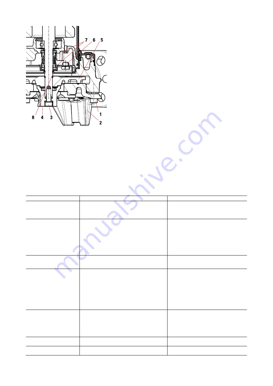
Fig. 8
10.1.
Checking and changing seal oil
•
Slacken and remove the 3 screws (1) and lift the pump base (2).
•
Use pliers to hold the grinder head and slacken it and remove the screw (3).
•
Remove the grinder head (4). Take the impeller (5) off the shaft.
•
Retrieve the tab, the sand guard ring (8) and the two fixing half-rings.
Slacken and remove the 4 body screws and lift off.
•
Now turn the pump upside down, unscrew and remove the cap (6). Tilt the pump
so as to drain the oil out of the hole of the cap (6) and pour it into a container.
•
Analyse the oil: if it contains water or abrasive particles (e.g. sand), check
the condition of the mechanical seal (7) and replace it if necessary (at a
specialised centre).
•
In the latter case also replace the oil with approx. 170 g of oil type
MARCOL 152 ESSO.
•
Restore the oil level inside the seal oil chamber by means of a special
funnel inserted in the hole of the cap (6).
•
Screw the cap (6) back into its seat and carry out the disassembly
operations in reverse order to reassemble the pump after having applied a
suitable amount of Teflon grease in the seat of the sand guard ring (8).
USED OIL MUST BE DISPOSED OF IN ACCORDANCE WITH CURRENT
REGULATIONS.
10.2.
Changing the grinder
See Fig.9 at the end of the booklet
10.3.
Cleaning the impeller
See Fig.10 at the end of the booklet
10.4.
Adjusting the impeller clearance
Proceed as follows:
1. Completely slacken the fixing screws.
2. Tighten the screws gently.
3. Tighten the retaining screws gently.
4. Slacken the screws by at least three turns.
5. Tighten the fixing screw by 180°.
6. Tighten the screws with a torque of 7 Nm.
11.
TROUBLESHOOTING
FAULTS
CHECKS (possible causes)
REMEDIES
The motor does not start and
does not make any noise.
Check that voltage is reaching the motor.
Check the protection fuses.
The float switch does not allow starting.
If burnt out, change them.
- Check that the float can move freely.
- Check that the float is efficient. (contact the
supplier).
The pump does not deliver.
The suction grid or the pipes are blocked.
The impeller is worn or blocked.
If installed on the delivery pipe, the check valve is
locked in the closed position.
The liquid level is too low. At start-up, the water level
must be higher than the filter level.
The head required is higher than the pump’s
characteristics.
Remove the obstructions.
Replace the impeller or remove the obstruction.
Check the proper operation of the valve and
replace it if necessary.
Adjust the cable length of the float switch.
(See paragraph “ADJUSTING THE FLOATING
SWITCH”).
The pump does not stop.
The float does not interrupt pump operation.
- Check that the float can move freely.
- Check the efficiency of the float (contacts may
be damaged - contact the supplier).
The flow rate is insufficient.
Check that the suction grid is not partially blocked.
Check that the impeller or the delivery pipe are not
partly blocked or encrusted.
Check that the impeller is not worn.
Ensure that the check valve (if contemplated) is not
partially blocked.
Check the direction of rotation in three-phase versions
(See paragraph “CHECKING THE DIRECTION OF
ROTATION”).
Remove any obstructions.
Remove any obstructions.
Change the impeller.
Accurately clean the check valve.
Invert two power supply wires.
The thermal overload protection
device stops the pump.
Check that the fluid to be pumped is not too dense as
it would cause overheating of the motor.
Check that the water temperature is not too high (see
liquid temperature range).
The pump is partially blocked by impurities.
The pump is mechanically blocked.
Clean the pump thoroughly.
Check for sliding between moving and fixed
parts; check the wear condition of the bearings
(contact the supplier).
The pump does not start.
Impeller blocked.
Remove the obstruction, wash and clean;
contact DAB Service if necessary.
Absorption higher than data
plate values.
Impeller blocked.
Remove the obstruction, wash and clean;
contact DAB Service if necessary.
Summary of Contents for FEKA VS GRINDER
Page 2: ...BAHASA INDONESIA Pag 1 ENGLISH Pag 7...
Page 14: ...DRAWINGS 12 Fig 9 Fig 10...


