INSTRUCTION MANUAL DAAB AUTOMATIC CONTROLL UNIT EP104 4.08
23
Instruction manual edition 1 for EP104 version 4.08
Commissioning
The process is the same for EP104-1 for one motor winder and EP104-2 for two motor winders.
The settings are changed as described in the section "Changing settings in the EP104".
An E on the far left of the display indicates an error message, see "Error messages". Note that the start-up values "EP-1" and
"EP-2" are not error messages.
Carry out the commissioning steps in the order shown – this will ensure that the channels are configured in the correct
sequence.
The automatic control unit is supplied in service mode with hold-to-run. Hold-to-run means that the motor runs while the
button is pressed, and stops when it is released.
The control unit will only work correctly if the following steps are carried out:
• Safety
!
Anyone commissioning the EP104 must have proven familiarity with, and understanding of, its functions, as well as
experience of commissioning control systems for the application to be used.
!
See "Settings" to find out how to read and configure values in the EP104.
Check that:
• All equipment is mechanically secured and installed according to the applicable instruction manuals.
• All components are correctly connected and installed by authorised installers before switching on the power supply.
• The necessary safety measures are in place to remove the risk of crushing and other risks relating to the controlled unit.
• Any necessary decoupling devices are installed in the controlled unit and that they work as intended.
Make sure you:
•
Discharge any static charge in your body by first touching an earthed object, for example the earth connection between the
door and the control unit, before changing settings or doing other work on the EP104.
• Take care when operating internal buttons to avoid touching live parts.
• Stop circuit
The stop circuit consists of a safety output, stop buttons and contactors. If the control unit detects a fault during the self test,
the power to the contractors is interrupted. The stop buttons are connected in series with the contactors, and they interrupt
the power to the contactors. If the STOP indication is lit green, the stop circuit is closed.
• Frequency converter
If the system is controlled using frequency converters, it must be operated according to the operating instructions for DB409
before you can continue with limit switches.
• Limit switch
Limit switches are used to inform the unit when the door is in the open or closed position. There are three limit switch options
to choose from: Encoders, which are electronic limit switches that detect the exact position of the door in degrees; mechanical
limit switches using cams that control microswitches; or, if the motor does not have any physical limit switches, timer control.
Encoder (electronic limit switch)
Right/left encoder position
L110=1, Motor 1 Left position
L120=2; Motor 2 Right position
L113
, Closed position
L123, Closed position
L112
, Open position
L122, Open position
L121, Position readout
L1
11, Position readout
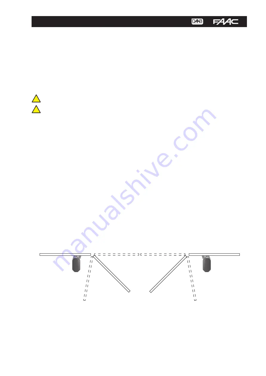
The encoder works by detecting the position of the door, and acts as an intelligent limit switch. Using a magnetic proximity
sensor, the EP104 calculates the precise position of the door. Limits for open and closed can be configured directly in the
automatic control unit in degrees instead of physically changing limit switch cams in the motor winders. It is possible to
commission one motor at a time by activating only one limit switch at a time. If L001 or L002 is set to 0, this motor will
not turn and the indicator will flash. If L001 or L002 is set to 4 (not both at the same time) and C033 is set to 5, it will
be possible for the motor to operate in hold-to-run with no restrictions and the limit switch indicators will flash quickly.
L110 and L120 must be selected to be able to read the angle positions in L111 and L121. Note also that in this mode
programmable inputs and radio are disabled.
Summary of Contents for EP104
Page 60: ......


