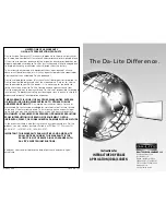
Da-Lite Polacoat Flex Plex, Instruction Book
The Da-Lite Polacoat Flex Plex is a versatile projection screen that delivers exceptional image quality. To help you make the most of this product, we provide a comprehensive instruction book or manual that you can download for free from our website. Discover seamless installation and optimal usage by accessing this invaluable resource today at manualshive.com.
Share
Download


Reviews:
No comments
Related manuals for Polacoat Flex Plex
SLATE Series
Brand: Qeedji Pages: 52
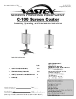
C-100
Brand: VASTEX Pages: 7
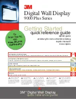
Digital Walldisplay 9000PD Plus
Brand: 3M Pages: 12
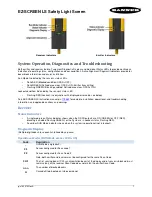
EZ-SCREEN LS
Brand: Banner Pages: 4
IDEA Screen
Brand: Da-Lite Pages: 2
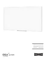
IDEA Screen
Brand: Da-Lite Pages: 8

ADVANTAGE DELUXE ELECTROL
Brand: Da-Lite Pages: 2

EXECUTIVE ELECTROL
Brand: Da-Lite Pages: 2

ADVANTAGE DELUXE ELECTROL
Brand: Da-Lite Pages: 2

TENSIONED EXECUTIVE ELECTROL
Brand: Da-Lite Pages: 2
Picture King
Brand: Da-Lite Pages: 16

ADVANTAGE ELECTROL
Brand: Da-Lite Pages: 2

ER Series
Brand: Neher Pages: 12
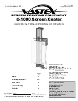
C-1000
Brand: VASTEX Pages: 8
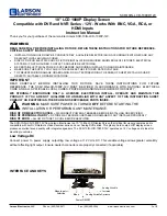
SCR-10IN-LCD-1080P-12V
Brand: Larson Electronics Pages: 2

VISAGE 770 SCREEN SYSTEM
Brand: Glasdon Pages: 4
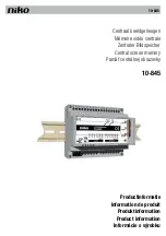
10-845
Brand: Niko Pages: 72
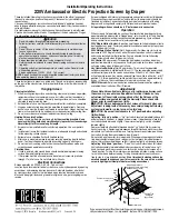
Ambassador 220V
Brand: Draper Pages: 2


