background image

3

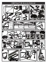
If your screen was shipped with the motor and roller already installed proceed to step 7.

1.   Remove the access door. First, remove the 2 bolts from each 

end with a 9/16" open wrench or socket driver. Next, use a 
5/32" hex key to remove the two screws in the center of the 
access door. This will allow the door to drop open on the hinges 
(Figure 1).

2.  Carefully unpack screen and roller assembly. Leave packing 

paper on the roller.

3.  Remove the square peg bracket from the motor end of the 

roller assembly (Figure 2). 

4.  Remove the safety clip from the motor attachement bracket 

located in the motor end of the screen housing.

5.  Use a 1/2" open wrench or socket driver to loosen the four bolts 

that secure pin end mounting bracket into housing. Lift pin end 
of roller into position and slide the bracket into the roller pin. 
Tighten all four bolts. Slide the pin end bracket towards the end 
of the case (Figure 3). 

6.   Place the roller assembly into the case with the motor on the 

left side. The limit switches should be facing down. Line up the 
head of the motor with the motor attachment bracket. 

7.  Complete electrical hook-up by snapping motor 1/3 wire 

connectors into case connectors (Figure 2).

8.  Return to motor end and insert safety clip over casting bracket 

to secure motor end.

9.  Carefully remove tape strips securing picture surface around 

roller. Slat should move freely. (Only if the roller assembly is pre 
installed.)


Caution! Do not Cut tape on fabriC with a knife 
or any sharp tool. remoVe by hanD.

10. Test installation by running screen up and down a few times. 

Be prepared to stop screen should any objects obstruct the 
movement of the screen. To prevent damage to the motor, the 
standard duty cycle is 1 minute on and 3 minutes off.

11. Re-install the access door. Procedure is the reverse of step 1 

listed above.

Tools required for screen and roller assembly:

sCreeN ANd roller AsseMBlY iNsTAllATioN

Bolts

Bolts

Figure 3

Figure 1

Figure 2

9/16“ Open Wrench 

or Socket Driver

1/2“ Open Wrench 

or Socket Driver

5/32“ Hex Key

Bolts

Access Door

Door Support Screws

Screen Motor

LVC Control Box

Screen Motor  
Limit Switches

Summary of Contents for Large advantage electrol

Page 1: ...Instruction Book for Large AdvantaGE ElectroL ...

Page 2: ... a knife or sharp object to cut tape you will damage the screen Pull orange string 5 Test installation by running screen up and down a few times Be prepared to stop screen should any objects obstruct the movement of the screen To prevent damage to the motor the standard duty cycle is 1 minute on and 3 minutes off CASE INSTALLATION IMPORTANT SAFETY INSTRUCTIONS When using your video equipment basic...

Page 3: ... motor on the left side The limit switches should be facing down Line up the head of the motor with the motor attachment bracket 7 Complete electrical hook up by snapping motor 1 3 wire connectors into case connectors Figure 2 8 Return to motor end and insert safety clip over casting bracket to secure motor end 9 Carefully remove tape strips securing picture surface around roller Slat should move ...

Page 4: ...ackets Electrical Junction Box Electrical Junction Box Screen Roller Access Door Audience Side Self Trimming Flange 2 3 16 Suggested 1 2 Threaded Rod Not Included Attached to Mounting Bracket Finished Ceiling Self Trimming Flange 12 3 16 13 1 8 11 9 1 8 11 7 16 10 15 16 ...

Page 5: ...ing picture surface approximately two feet then lower again Repeat until desired picture surface position is attained CAUTION Do not adjust for more drop than what was ordered At least 1 1 2 wraps of fabric must remain on the roller This screen comes standard with 0 or 2 black at the top See the specification data sheet for details 1 Raise picture surface approximately two feet above desired level...

Page 6: ...e 3 position high voltage rocker switch with this unit This will damage the low voltage control board Eye Port Plug IR or RF Remote Here Power Input 120VAC 60Hz Black Hot White Common White Common Black Down Red Up Green Ground Screen Motor Red Up White Common Black Down Front of Wall Switch Back of Wall Switch Green Ground White Common Black Down Red Up Green Ground ...

Page 7: ...ge rocker switch with this unit This will damage the low voltage control board Eye Port Plug IR or RF Remote Here Power Input 120VAC 60Hz Brown Hot White Common Screen Motor Red Up Blue Common Black Down Front of Wall Switch Back of Wall Switch Green Yellow Ground Green Yellow Ground Blue Common Brown Down Black Up Black Blue Common Brown Down Black Up Green Yellow Ground Wire Nut Wire Nut ...

Page 8: ... Screen will not operate and motor does not hum Power at junction box Thermal overload tripped Let motor cool down for 15 minutes Try again Broken wire in the down or up position Check for continuity Cut off old splice and reconnect Defective motor limit switch or capacitor Replace motor assembly NOTE Motor is a sealed assembly Capacitor burned out Replace motor assembly Screen does not stop at co...

Page 9: ...9 ...

Page 10: ...10 ...

Page 11: ...11 ...

Page 12: ...uct and prepay all transportation expenses THIS WARRANTY IS IN LIEU OF ALL OTHER WARRANTIES EXPRESS OR IMPLIED INCLUDING WARRANTIES AS TO FITNESS FOR USE AND MERCHANT ABILITY Any implied warranties of fitness for use or merchantability that may be mandated by statute or rule of law are limited to the five 5 year warranty period This warranty gives you specific legal rights and you may also have ot...

Reviews: