background image

Thank you for your purchase of the PLUS Copyboard. 

Please read this User’s Manual carefully before use to take full advan-

tage of the functions of this product. After you have finished reading 

the manual, please keep it for future reference. 

Copyboard

M-17S/M-17W

User’s Manual

Summary of Contents for M-17S

Page 1: ...LUS Copyboard Please read this User s Manual carefully before use to take full advan tage of the functions of this product After you have finished reading the manual please keep it for future reference Copyboard M 17S M 17W User s Manual ...

Page 2: ...t trademarks even when not written down will be given due respect Product names and company names appearing in this manual are registered trademarks or trademarks of the respective companies 1 The contents of this manual may not be reprinted in part or whole without permission 2 The contents of this manual are subject to change without notice 3 Great care has been taken in the creation of this man...

Page 3: ...onnected to a computer 19 Making the Device Settings 20 Meaning of Error Messages 23 Troubleshooting 24 Specifications 26 Appendix 27 Connections and Wiring Diagram 27 Meaning of the Terms Used in this Manual Main unit or set This refers to the copyboard USB memory refers to USB flash memory USB memory storage means the saving of sheet surface data using MEMORY i e the USB port of the operation pa...

Page 4: ...ing Copyboard Accessories Dedicated markers One each of black and red Use these markers to draw on the sheet surface AC power adapter with power cord 1 This is the power adapter for supplying power to the copy board See Page E 10 LTE36E S2 3 USB cable type B type A 1 PLUS code 715258900 Cable for connecting the main unit to a computer Used for making the device settings Do not use this cable for c...

Page 5: ...ter here See the Assembly and Setup Manual Stand This stand supports the copyboard See the Assembly and Setup Manual Main unit Names of the Parts Front Pen tray Depending on the product you have purchased the printer may be sold separately This illustration does not show the connection cords Effective Reading Size The area that can be copied is the gray area of the diagram It might not be possible...

Page 6: ...nal computer PC dedicated USB port Type B Connect this with the USB port type A of the PC Used to connect the copyboard to a computer to make the copyboard s device settings Can also be used to copy scanned images onto the computer See page E 19 E 20 Printer connector USB port Type A Connect this with the USB connector of the printer See Page E 27 The printer connector is dedicated for use with a ...

Page 7: ...nd s casters by pressing the bottom of the caster lock button If not the stand could move while the main unit is being mounted or removed resulting in accidental injury After unplugging the power cord from the wall power outlet disconnect all the connection cords from the set s input output terminals If the set is removed without disconnecting the cords it could tip resulting in accidental injury ...

Page 8: ... When connected to a computer by USB cable the image is stored in the copyboard s internal memory 6 Scroll Stop button Scrolls the sheet one screen portion left then stops auto matically A press of this button while scrolling will stop the scrolling 7 USB A Memory port USB Type A Saves in commercially available USB memory images that have been read by the copyboard 8 Status These indicators light ...

Page 9: ...Press the copyboard s ON Standby button to turn the power on 2 Connect the copyboard to the computer using the PC dedicated USB port 3 Press the Save button 4 The image is saved on the computer When connecting the power plug the flashing LED indicator in the display window starts to rotate for about 5 seconds Make sure to press the On Standby button to power on the copyboard when the flashing LED ...

Page 10: ... use the copyboard connect the copyboard s AC power plug to a wall power outlet The main power turns on In this manual this is referred to as the standby mode The descriptions in this manual assume that the AC power plug is connected that the unit is in the standby mode About the printer s power supply When using a printer connect its power plug to a wall power outlet Also turn on the printer s po...

Page 11: ...y until it touches the paper See your printer s operating instructions for a description of the paper that can be used Switch on the power Press the power switch The power indicator lights This completes the preparation of the printer Press the B W Print button on the copyboard s control panel One page worth of data is read and the printing operation starts Depending on the printer indicators etc ...

Page 12: ... Basic Printing Operation The one screen that is visible is printable position To fine adjust the sheet surface position with the sheet stopped move the sheet slowly by hand The sheet can be moved either to the left or to the right Printing of the portion located around the sheet surface might not be possible Please see Effective reading size on Page E 5 01 is selected when the power is turned on ...

Page 13: ...lace your hand at the vertical center and move the sheet slowly Quick movement can cause damage to the drive mechanism of the copyboard If the ON Standby button is pressed while the sheet surface is being read printing is interrupted and only part of the image will be printed To move the sheet surface wait until scrolling stops then press the Scroll Stop button The one screen portion is reduced to...

Page 14: ...artitions only one partition can be recognized with this unit See the PLUS website for more information on USB memory devices usable with this unit Using USB Memory The content of what has been drawn on the sheet surface of the copyboard can be saved in USB memory Later the saved image can be read into a personal computer and made into a document of the proceedings of the meeting or affixed to a d...

Page 15: ... When the copyboard and a computer are connected by USB cable the data is stored in the main unit s inter nal memory Letters and diagrams drawn with color markers are stored as grayscale images The 5 second flashing US display indicates that the USB memory has not been inserted Please insert the USB memory and then press the Save button A 5 second flashing FL display indicates that there is insuff...

Page 16: ...s follow for saving the image files in the USB memory device to the hard disk of the personal computer and for deleting the folder when the USB memory capacity is full There are various methods that can be used for saving and deleting including the use of Explorer See the instruction manual of your personal computer or the software that you are using for information about using a personal computer...

Page 17: ...n the USB device is connected to a USB hub or when it is connected using an extension cable Notice Deleting USB memory image files with the computer Before deleting important image files be sure to save them on the computer as a data backup 1 Open My Computer or Computer and then open the drive icon which shows USB memory The folder named CB_image contains the memory storage data of the copyboard ...

Page 18: ...stem 2 Click OK when The USB Mass storage Device device can now be safely removed from the System is displayed When using Windows XP Windows Vista Windows 7 OK does not appear on the message screen Simply disconnect 3 This allows the USB memory device to be unplugged from the computer Do not disconnect the USB memory device while the USB memory device s access indicator is flashing Doing so will d...

Page 19: ...Copy the CBImage jpg file to My Documents etc on the computer To disconnect the USB cable follow the procedure in step 3 on the previous page Only one sheet s worth of data can be stored in the copyboard s internal memory When the storage procedure is performed successively on the copyboard the data is overwritten The image data in the copyboard s internal memory is cleared when the USB connection...

Page 20: ...en In this case open the setting ini file in text format using Notepad or another application on the computer and rewrite the contents of the settings file directly See page E 22 Turn on the copyboard s power and connect the PC dedicated USB port type B and com puter using the USB cable Usually with Windows XP Windows Vista Windows 7 the standard driver is installed automatically and the copy boar...

Page 21: ...ng range Equal ratio 145 x 287 Compressed 195 x 287 Letter size printing range Equal ratio 136 x 269 Compressed 206 x 269 North America Letter Others A4 Printing Image This is only selectable on wide type copyboards This selects the vertical horizontal aspect ratio of the image when printing Original Image Image is printed with the same aspect ratio as on the copyboard s sheet surface Match Paper ...

Page 22: ...e image to the printing paper Only settable for wide type copyboards See the previous page for details on the settings Do not input spaces If this is done the file will be recognized as corrupt when the copyboard is started and the settings well be reset to the defaults 1 After the file has been rewritten save it overwriting the previous setting ini settings file Save to location setup folder for ...

Page 23: ...during USB memory storage Please perform USB memory storage again Do not insert or remove the USB memory during processing Reading problem There is a lighting fault of the reading light source or a read signal error Unplug the power plug from the power outlet and then plug it in again System error There is a memory or internal fault Unplug the power plug from the power outlet and then plug it in a...

Page 24: ...the PC The date is not updated The copyboard s battery is dead Contact your store of purchase If the problem persists please contact your nearby PLUS Corporation sales office dealer or store Condition Please Check Printer Related The copyboard s power turns on but the printer s power does not Check whether the printer s power plug DC plug is securely inserted If the power still does not turn on di...

Page 25: ...rayscale lines displayed uniformly Are there any missing dots blurred lines etc Remedy If the nozzle is partially choked clean it If the quality of the print does not improve even though the nozzle has been cleaned wipe off the ink on the surface of te nozzle For details see the User s Guide included with the printer Please see your printer manual for information about printing problems printer ma...

Page 26: ...Clock Used for the timestamp and for file dating properties Includes backup battery for when there is a loss of power Battery life Approx 00 hours PC connection Images can be acquired and device settings made via USB using a browser Power supply AC power adapter Input AC100 240V 50 60 Hz Max 0 75 A Output DC 12 V 3 0 A Power consumption In standby 3W During operation 12W not including printer Oper...

Page 27: ... the printer Appendix The connections and wiring diagram below is included here for checking the connections Copyboard and Printer Connections Diagram Appearance of printer is for illustration purposes Connections and Wiring Diagram The AC power adapters of accessories and printers that have been verified to be operation many differ from the ones shown on the connections diagram they may be of the...

Page 28: ...26 4613 12A ...
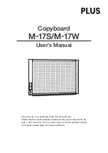
Reviews: