background image

8

CONTOUR

®

 ELECTROL

®

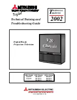
 INSTALLATION FOR 240V SCREENS

5/12 Volt Screen Trigger 
on Projector

240VAC/ 50Hz  
Power Source

Red

Red

Black

Black

Brown (Hot)

Green/Yellow (Ground)
Brown (Down)
Blue (Common)
Black (Up)

Green/Yellow 
(Ground)

Blue (Common)

Front of Wall 

Switch

Back of

Wall Switch

White

240V Wiring DiagraM


iMportant note:

 The wall switch is ReQUIReD to make 

any limit switch adjustments, eVeN if a third party control 
system is used. Therefore, it is advised to wire the switch or 
provide a 4-conductor connection that is accessible.

ilt rJ-9 pin-outs 

(Tab Is Facing Up)

Ground Common

IR or Up

+5V

Data or Down

Red

Green

White

Black

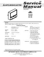
240V Wiring DiagraM With  optional Built-in ViDeo proJeCtor interFaCe


Caution: the proJeCtor Must Be turneD oFF 
BeFore ConneCting the trigger Wires to the 
proJeCtor. Failure to Do so May DaMage the 
Controller.

1.  Use 2-conductor 20-24 gauge wire to extend the low voltage 

connection from the projector’s 5 or 12-volt screen trigger 
output to the length required to reach the VPI. When 
extending the low voltage connection from the projector’s 
screen trigger output, be sure to maintain the proper polarity. 
The red wire from the VPI is the “signal” and the black wire 
from the VPI is the “ground”.

2.  Connect the wires from the VPI that are labeled “Low 

Voltage Connection” to the end of the extended screen 
trigger wires above.


iMportant note:

 The wall switch is ReQUIReD to make 

any limit switch adjustments, eVeN if a third party control 
system is used. Therefore, it is advised to wire the switch or 
provide a 4-conductor connection that is accessible.

UP DN

UP +5V COM DN

UP

STOP

DOWN

GND 

+5V

3-POSITION 
SWITCH

RJ9

RJ9

RJ9

Motor

Front of Wall 

Switch

Splitter  

Dry Contacts

Back of

Wall Switch

Green

Brown (Hot)

Blue (Common)

NOTe: Ground–Must be 
Connected to Building Ground

Ground to Case

Green

power input  
240VaC / 50hz

Summary of Contents for Contour Electrol

Page 1: ...Instruction Book for ContouR Elecol ...

Page 2: ...t Items inside will be used during installation Note Remove the black tape and rubber bands from the slat bar after the case has been installed There are three ways to install the Contour Electrol Wall Mount Ceiling Mount or Ceiling Hook Procedures for each method are as follows Wall Mount 1 Using a 2 Phillips screwdriver loosen the two stop screws and remove the wall mount bracket from the back s...

Page 3: ...the ceiling has adequate reinforcement 6 Hold the screen case up to the ceiling and mark the hole locations The brackets have a set of front holes and a set of rear holes Attach the Contour Electrol using the appropriate hardware for your ceiling type It is best to use at least one hole in each set Ceiling Hook Mount 1 The ceiling hook mount brackets are tied together and attached to the ceiling f...

Page 4: ...ox cover NOTE Must be installed in accordance with the requirements of the Local Building Codes the Canadian Electrical Code CEC CAN CSA C22 1 and the National Electric Code NEC NFPA 70 2 Test installation by running screen up and down a few times Be prepared to stop screen should any objects obstruct the movement of the screen To prevent damage to the motor the standard duty cycle is 1 minute on ...

Page 5: ...ase the up or down buttons on the switch to operate the screen 6 Replace the switch and cover plate on the wall Important Note The wall switch is REQUIRED to make any limit switch adjustments even if a third party control system is used Therefore it is advised to wire the switch or provide a 3 conductor connection that is accessible CAUTION Do not adjust for more drop than what was ordered At leas...

Page 6: ...AGRAM 3 conductor 20 24 gauge wire can be used in place of the supplied RJ 14 cable to connect the wall switch Connect the BUS terminals on the wall switch to the corresponding BUS terminals on the splitter board IMPORTANT Note The wall switch is REQUIRED to make any limit switch adjustments EVEN if a third party control system is used Therefore it is advised to wire the switch or provide a 3 cond...

Page 7: ...be turned off before connecting the trigger wires to the projector Failure to do so may damage the controller Use 2 conductor 20 24 gauge wire to extend the low voltage connection from the projector s 5 or 12 volt screen trigger output to the length required to reach the VPI When extending the low voltage connection from the projector s screen trigger output polarity does not matter The red and bl...

Page 8: ... the controller 1 Use 2 conductor 20 24 gauge wire to extend the low voltage connection from the projector s 5 or 12 volt screen trigger output to the length required to reach the VPI When extending the low voltage connection from the projector s screen trigger output be sure to maintain the proper polarity The red wire from the VPI is the signal and the black wire from the VPI is the ground 2 Con...

Page 9: ...d tripped Let motor cool down for 15 minutes Try again Broken wire in the down or up position Check for continuity Cut off old splice and reconnect Defective motor limit switch or capacitor Replace motor assembly NOTE Motor is a sealed assembly Capacitor burned out Replace motor assembly Incorrect stopping position in downward direction Lost roller wrap See instructions below Down limit switch out...

Page 10: ...10 ...

Page 11: ...11 ...

Page 12: ... necessary for the dealer to return the screen or part to Da Lite transportation expenses to and from Da Lite are payable by the purchaser and Da Lite is not responsible for damage in shipment To protect yourself against damage or loss in transit insure the product and prepay all transportation expenses THIS WARRANTY IS IN LIEU OF ALL OTHER WARRANTIES EXPRESS OR IMPLIED INCLUDING WARRANTIES AS TO ...

Reviews: