background image


Document Number: 

V013421_05_MiniRad-V_Manual_Installation_Instructions 

Date: 

8/28/2019 

Page: 

7 of 13 

D-tect Systems 

 11814 South Election Rd. Suite 200, Draper, UT  84020 

 (801) 260-4000 


5.4  Installing the Mini Rad-V Cables 


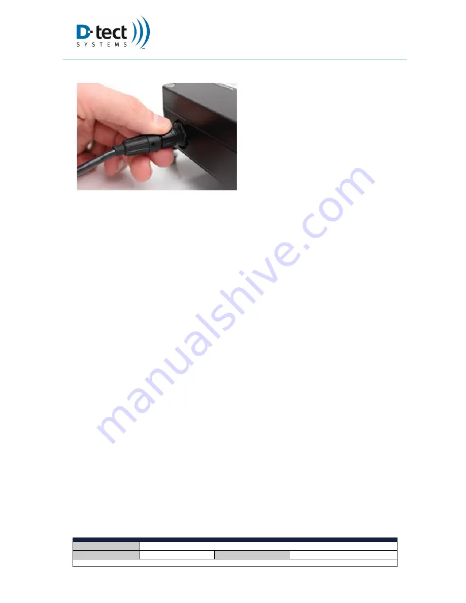
Figure 7: Installing Cables 

  The  modules  are  connected  by  the 

communication cable (included). 

  To connect the cable, adjust it until it fits 

onto  the  post,  then  turn  the  cable 
connector  until  it  locks  firmly  into  the 
post. 

  Make  sure  that  the  cables  do  not 

interfere  with  the  vehicle’s  other 
operating systems. 

  Do  not  place  excessive  force  on  the 

cables or the connectors. 

  Do not route cables where they may be 

pinched, worn excessively, or melted. 


Summary of Contents for Mini Rad-V

Page 1: ...13 D tect Systems 11814 South Election Rd Suite 200 Draper UT 84020 801 260 4000 INSTALLATION AND OPERATING INSTRUCTIONS FOR THE VEHICLE MOUNTED RADIATION DETECTION SYSTEM Generation 2 Version 5 Augus...

Page 2: ...s been included to mitigate the collection of snow ice and moisture on the Exterior Detector housing The entire installation process was re evaluated as well and is now simpler and more straightforwar...

Page 3: ...structions Date 8 28 2019 Page 3 of 13 D tect Systems 11814 South Election Rd Suite 200 Draper UT 84020 801 260 4000 Figure 1 In Cab Display Module Figure 2 External Detector Module Figure 4 External...

Page 4: ...afely with mild soap and water using a warm wet cloth 5 Installation Instructions Please refer to your vehicle manufacturer s manual for specific installation guidance for your vehicle particularly fo...

Page 5: ...ached to the vehicle with four screws spaced 2 apart on both ends of the module The sensitivity of the device decreases with the amount of material between the detector and any potential radiation sou...

Page 6: ...of the driver or interfere with vehicle controls and or other equipment Contact your local Department of Transportation for information regarding regulations for dashboard mounted displays as these m...

Page 7: ...nstalling Cables The modules are connected by the communication cable included To connect the cable adjust it until it fits onto the post then turn the cable connector until it locks firmly into the p...

Page 8: ...the blue LED will flash to indicate the 30 second calibration phase When calibration is complete the Mini Rad V will beep once more and go into detection mode This keeps the Mini Rad V at maximum sens...

Page 9: ...viewing Alarm Loud audible alarm with acknowledge button Alarm Volume 90 dB at 10 cm Power 12V DC Energy Range 30 keV 3 MeV Environment In Cab Display Controlled environment operates in high RF envir...

Page 10: ...radiation levels it will recalibrate N A While the blue light is on the red light begins to flash and the audio begins to beep This is the expected behavior when detecting the presence of gamma and x...

Page 11: ...place or refund the purchase price of any Products that do not conform with this warranty Repair may include the replacement of parts with functionally equivalent reconditioned or new parts Replacemen...

Page 12: ...PURCHASE PRICE OF THE PRODUCT OR FOR ANY INDIRECT INCIDENTAL SPECIAL OR CONSEQUENTIAL DAMAGES ARISING OUT OF THE USE OR INABILITY TO USE THE PRODUCT TO THE FULL EXTENT THESE DAMAGES MAY BE DISCLAIMED...

Page 13: ...rts of them Laws in the United States and other countries preserve for D tect Systems certain exclusive rights for copyrighted D tect Systems software such as the exclusive rights to reproduce in copi...

Reviews: