2
Quick Installation Guide
ENGLISH
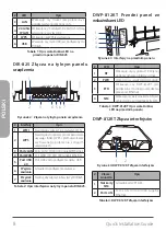
DWP-812KT Rear Panel
LED Indicators
RF
PWR
ETH
SIM
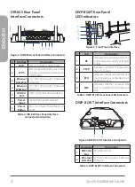
Figure 3: Front Panel Interface
#
LED
Description
1
RF
Indicates the strength of the LTE
signal. More bars signify a stronger
signal.
2
PWR
Indicates whether the device is
receiving power.
3
ETH
Indicates whether the DWP-812KT
is connected to another device on
its Ethernet port.
4
SIM
Indicates whether an active SIM
card is inserted into the SIM card
slot.
Table 3: DWP-812KT Rear Panel LED Indicators
DWP-812KT Interface Connectors
Figure 4: DWP-812KT Interface Connectors
# Connector
Description
1
SIM Card
Slot
2FF SIM card slot.
2
Ethernet
LAN Port
10/100/1000 Gigabit Ethernet
LAN port.
Table 4: DWP-812KT Interface Connectors
DIR-825 Rear Panel
Interface Connectors
LAN4
LAN3
LAN2
LAN1
WAN
USB
WPS
WiFi
POWER
- • +
Figure 2: DIR-825 Rear Panel Interface Connectors
#
Interface
Description
1
WIFI
Press to enable or disable Wi-Fi.
2
WPS
Press to start the WPS process and
create an encrypted connection to
a WPS client.
3
Ethernet
LAN Ports
10/100/1000 Gigabit Ethernet
LAN ports.
4
Ethernet
WAN Port
10/100/1000 Gigabit Ethernet
WAN port.
5
USB 2.0
Port
USB 2.0 port for a storage device.
6
Power
Input
Input for the power adapter.
7
Power
Button
Press to power the DIR-825 on
or off.
Table 2: DIR-825 Rear Panel Interface
Connector Descriptions
1
2
3
4 5 6 7
1
2
1
2
3
4

