background image


116 

Chapter 3   Managing Volumes 

2.  Perform one of the following steps to remove the port from the group: 

– 

On the Network menu, click Remove Port from Group. 

– 

In the Network Actions panel, click Remove Port from Group. 

– 

Press the right mouse button and click Remove Port from Group from the shortcut 
menu. 

3.  Record your settings in Table C-3. 

7.6 Working with VLANs 

iSCSI performance can be improved through careful logical and physical separation. For 
example, iSCSI SAN traffic should never be mixed with ordinary Ethernet user traffic. This 
not only impairs SAN performance, but also creates a potential security risk since storage 
data is accessible on the user LAN. Instead, iSCSI SAN traffic should be isolated from the 
everyday user traffic. The most common method of separation is creating a virtual LAN 
(VLAN). A VLAN limits iSCSI traffic to the virtual LAN and keeps out regular traffic. 

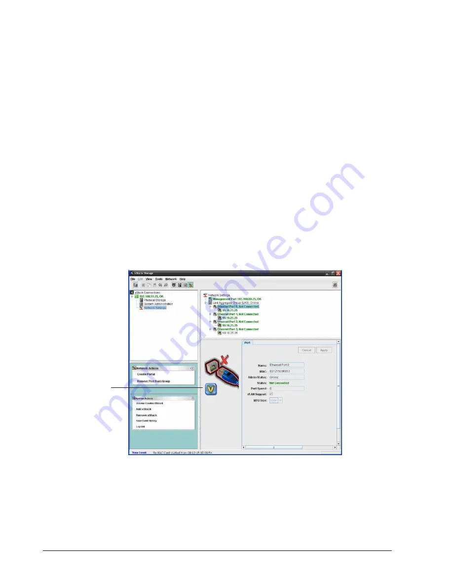
Using the xStack Storage Management Center, you can VLAN-enable ports and LAGs. To 
differentiate between ports and LAGs that are and are not VLAN-enabled, the port or LAG 
icon to the left of the Detail Tabs displays a V when a VLAN-enabled port or LAG is clicked in 
the Main Display (see Figure 7-11).  


Figure 7-11. VLAN-Enabled Port 

When you VLAN-enable a port or LAG, the portal information associated with the port or LAG 
is deleted prior to the port or LAG joining the VLAN. As a result, any IP address associated 
with the port or LAG is removed. The same scenario occurs if a VLAN-enabled port or LAG is 
removed from the VLAN. 

This “V” indicates that 

the port selected in the 

Main Display is VLAN 

enabled 

Summary of Contents for DSN-5410-10 - xStack Storage Area Network Array Hard...

Page 1: ...D Link xStack Storage iSCSI SAN Arrays Managed SAN Solutions DSN 5000 Series DSN 5110 10 5210 10 5410 10 5000 10 Management Center Software User s Guide Version 1 3 ...

Page 2: ...e without notice The only warranties for D Link products and services are set forth in the express warranty statements accompanying such products and services Nothing herein should be construed as constituting an additional warranty D Link shall not be liable for technical or editorial errors or omissions contained herein Copyright 2010 D Link Systems Inc Trademarks Includes one or more of the fol...

Page 3: ...mpliance questions Document Revision Level Revision Date Description 1 0 July 2008 Version 1 0 Initial release based on Software version 2 0 0 1 1 September 2008 Version 1 1 Updated for software version 2 5 0 and redundant controller support 1 2 January 2009 Version 1 2 Updated for software version 2 5 1 and minor formatting corrections 1 3 May 2010 Version 1 3 Updated for software version 2 7 0 a...

Page 4: ...ent assumes that the user is computer literate familiar with storage array products and has a basic understanding of storage products and concepts Typographic Conventions Notes Notes provide information that deserves special attention They are preceded by Cautions Cautions contain information which if not followed can cause damage to the xStack Storage array and possible loss of data They are prec...

Page 5: ...rt through our website or by phone Tech Support for customers within the United States D Link Technical Support over the Telephone Please see our support site for current number http support dlink com Monday to Friday 8 00am 5 00pm PST PDT D Link Technical Support over the Internet http support dlink com Tech Support for customers within Canada D Link Technical Support over the Telephone Please se...

Page 6: ... 10 2 3 1 Understanding the User Interface 11 2 3 2 Menu Bar and Toolbar 11 2 3 3 View Panel 13 2 3 4 Main Display 14 2 3 5 Action Panels 14 2 3 6 Detail Tabs 15 2 3 7 Status Bar 15 2 4 Getting Help 15 2 5 READ THIS SECTION If You Read Nothing Else In This Guide 16 Chapter 3 Getting Started 17 3 1 Connecting and Logging In 18 3 1 1 Using the Start up Wizard 18 3 1 2 Logging in from the Home Page 2...

Page 7: ...izing a Drive 73 5 2 2 Downing a Drive 74 5 2 3 Reserving Spare Drives 75 5 3 Using the Detail Tabs 76 5 3 1 Viewing Drive Properties Properties Tab 76 5 3 2 Viewing Extents on a Drive Extents Tab 77 5 3 3 Viewing SMART Data and Attributes SMART Data and SMART Attributes Tabs 78 Chapter 6 System Administration 81 6 1 Understanding the System Administration View 82 6 1 1 Single Controller Systems 8...

Page 8: ...ming System Actions 119 8 1 Adding an xStack Storage 119 8 2 Removing an xStack Storage 120 8 3 Force System Failover 121 Chapter 9 Best Practices 123 9 1 Saving Configuration Settings 124 9 2 Resetting Display Preferences 124 9 3 Working with Firewalls 124 Chapter 10 Troubleshooting 127 10 1 Downloading a System Diagnostic Capture 128 10 2 Possible Problems and Recommended Corrective Actions 129 ...

Page 9: ...xStack Storage Management Center Software User s Guide ix This Page Left Intentionally Blank ...

Page 10: ......

Page 11: ...cepts associated with it Topics in this chapter include Section 1 1 Product Overview Section 1 2 Terminology and Concepts Section 1 3 Storage Pools and Drives Section 1 4 Volumes Section 1 5 Tasks Section 1 6 Network Portals Section 1 7 VLANs Section 1 8 LAGs Section 1 9 iSCSI Target Nodes Section 1 10 iSCSI Log In Sessions and Connections Section 1 11 Multiple Connections per Session ...

Page 12: ...features such as battery policy settings and SNMP settings can also be set 1 2 Terminology and Concepts The purpose of the xStack Storage system is to virtualize disk storage for use by a customer s host computers servers At its front end the xStack Storage system uses the iSCSI protocol over Ethernet to connect to the customer s servers At its back end the xStack Storage system connects to a bank...

Page 13: ...m will act as the target Traditionally a local SCSI bus connects a single initiator to up to seven targets but a SAN allows an unlimited number of each The initiator s iSCSI stack packs SCSI commands and data into IP packets which are then unpacked by the target for processing as if they had originated locally The iSCSI protocol defines two types of iSCSI Nodes The initiator node The target node T...

Page 14: ...nistrator to make the drive available for use which automatically moves the drive to the Available Pool When a new system is installed all new drives are placed in the Available Pool The drives remain in the Available Pool until they are needed for use in a volume 1 4 Volumes A volume is a set of blocks of storage that are organized and presented for use by a customer s server an iSCSI initiator n...

Page 15: ... organization and reserves one chunk from each stripe to hold the parity information The parity information provides redundancy without having to keep a complete copy of the data If any single drive fails the parity calculation mechanism can be applied to the data on the remaining drives to provide full access reading and writing of all data Further the parity calculation mechanism can be used to ...

Page 16: ... 1 5 Tasks The xStack Storage system can automatically or at your demand perform activities that take time and consume the controller s resources You can control to some degree when tasks are performed You can suspend and resume any task Some tasks can be cancelled and some can be scheduled on a recurring periodic interval The xStack Storage system can perform the tasks described in the following ...

Page 17: ...task can be suspended and resumed but it cannot be cancelled An initiator can access the new space in a volume while the Grow task is being performed 1 5 5 Reconfigure a Volume The xStack Storage system allows Administrators to change the RAID characteristics and or size of an existing volume When you reconfigure a volume you can specify the RAID organization hard disk drives to be used stripe wid...

Page 18: ...lace the standard one to one relationship of Ethernet port to Network Portal with a LAG LACP protocols are not supported Static LAG configurations are the only supported option 1 9 iSCSI Target Nodes An iSCSI target node is the method of providing a permissible access to storage on an xStack Storage system One target node is automatically generated for each volume The target node name includes the...

Page 19: ...while enjoying lower total cost of ownership This User s Guide describes how to use the xStack Storage Management Center to configure provision and manage the storage on xStack Storage arrays It includes an overview of the xStack Storage Management Center a description of its user interface and step by step instructions for performing configuration and management activities 2 1 Key Features The fo...

Page 20: ...wall environment 2 3 Understanding the Basics The xStack Storage Management Center is a graphical Web based interface used to perform centralized storage configuration management administrative and network activities for one or more xStack Storage systems see Figure 2 1 These activities are performed in their own screens or views The xStack Storage Management Center supports the following four vie...

Page 21: ...ange when you switch views If you switch from Volume View to Physical Storage View the Volume menu changes to Storage and all the volume related commands in the Volume menu change to commands relevant to managing the physical storage on the xStack Storage The toolbar appears below the menu bar and provides buttons for frequently performed activities in the current view If you place the pointer ove...

Page 22: ...enience some tasks can also be performed by pressing the right mouse button and clicking an option from a shortcut menu that appears In Volume View for example selecting a volume in the Main Display and pressing the right mouse button displays the shortcut menu in Figure 2 4 You can then select an option from the shortcut menu to perform the desired task Figure 2 4 Shortcut Menu for Volume View Ma...

Page 23: ...rating status In the View panel in Figure 2 5 the xStack Storage corresponding to IP address 192 168 59 25 is being managed The checkmark and OK next to this IP address and the green color coding of the IP address itself indicate that this xStack Storage is operating normally When the IP address of the currently managed xStack Storage is highlighted the Volume View is displayed Below the IP addres...

Page 24: ...e from the current view In Volume View for example the top panel becomes the Volume Actions panel and contains actions associated with volumes If you switch to Physical Storage View the tops panel changes to the Drive Actions panel and displays actions related to drives If there are no actions available for the current view such as in System Administrator View the top panel disappears There are ti...

Page 25: ... the status bar On the right side of the status bar is an activity indicator that moves from side to side to indicate when activity is being performed otherwise the activity indicator sits dormant For users who prefer the status bar to be hidden uncheck Show Status Bar on the View menu Figure 2 9 Status Bar 2 4 Getting Help The xStack Storage Management Center provides a comprehensive online help ...

Page 26: ...r for the first time 3 1 2 Complete the Start up Wizard first time login only 3 1 1 3 Change the default admin login password 3 4 1 4 Set up users if users other than the administrator will be accessing the xStack Storage Management Center 3 4 2 5 Create one or more volumes 4 2 6 Grant access to all initiators 4 3 1 Recommended Tasks 1 Save the configuration file 6 2 5 2 Grant individual iSCSI ini...

Page 27: ...chapter are Section 3 1 Connecting and Logging In Section 3 2 Setting the System Date and Time Section 3 3 Customizing the Date and Time Section 3 4 Configuring User Accounts Section 3 5 Logging Out Section 3 6 Exiting the xStack Storage Management Center Section 3 7 Shutting Down the xStack Storage Array Before proceeding be sure all the minimum system requirements in section 2 2 have been met ...

Page 28: ...Continue to this website option to proceed Figure 3 1 Certificate Warning 3 One of the following actions occurs For your initial login the Start up Wizard appears and you should proceed to section 3 1 1 For all subsequent logins the home page appears and you should proceed to section 3 1 2 3 1 1 Using the Start up Wizard The xStack Storage Management Center provides a straightforward easy to use S...

Page 29: ...m for initial use 1 Click the I Accept the End User License Agreement button on the Welcome screen The Admin Account page in Figure 3 3 appears You must accept the End User License Agreement to proceed with the Start up Wizard To download the End User License Agreement to your computer click Click here to download the End User License Agreement on the Welcome screen ...

Page 30: ... set up after completing the initial Start up Wizard If you want to change the default password type a case sensitive password in the Password field and then retype the same password in the Re type Password field For security each typed password character appears as a bullet Record the admin password in Table C 6 3 Click Next to continue The Management Port page appears see Figure 3 4 ...

Page 31: ... the xStack Storage management port The settings you specify must be compatible with your local network and accessible to client computers that may be used to access the xStack Storage Management Center By default the host name is blank and you should change this to one that is more meaningful 5 Click Next to continue The Data Port page appears once for each data port on your system see Figure 3 5...

Page 32: ... optional To skip this screen click Skip to Email Notification However if you skip this screen you will need to specify these addresses through the xStack Storage Management Center before you can use the data ports If you specify these settings now record them in Table C 9 and click Next when finished After skipping or completing the fields on the Data Ports page the Email Notification page appear...

Page 33: ...ss where email messages are to be sent Enter the required settings and record them in Table C 10 Entering this information at this time is optional you can enable Email Notification at a later time using the Advanced Settings tab in the System Administration View refer to section 6 2 13 If you wish to have multiple recipients for the e mail notifications you must create an alias e mail address on ...

Page 34: ...etes the Start up Wizard After the storage system restarts the home page appears see section 3 1 2 3 1 2 Logging in from the Home Page The xStack Storage Management Center home page has the following three links see Figure 3 8 Click here to run the xStack Storage Management Center now displays a log in screen similar to the one in Figure 3 9 If you are having problems starting the xStack Storage M...

Page 35: ...est version of JRE is not installed on the management PC xStack Storage will let you download it if the PC has Internet access The minimum version of JRE is v1 6 0 0 1 In the View panel click the xStack Storage you want to log in to if it is not already selected 2 Enter your username and case sensitive password in the appropriate text boxes The first time you log in use the following default usern...

Page 36: ...e IP address of the xStack Storage you want to log in to and click Log In from the shortcut menu A connection message appears as you log in to the xStack Storage then the Volume View is displayed 3 2 Setting the System Date and Time The xStack Storage maintains the current date and time You may need to change these settings the first time you configure the xStack Storage if time changes occur in y...

Page 37: ...click on the calendar button at the far right of the date and time field to display a calendar pop up to simplify the date selection an example is shown in Figure 3 11 Figure 3 11 Calendar Pop Up Dialog Box 4 Alternatively you can double click on the NTP Time Server IP Address item and enter an IP address for a third party NTP server or you can click on the Synchronize Remote Time button to get th...

Page 38: ...edure from any view 1 On the Tools menu click Customize Time Display The Customize Time Display dialog box appears see Figure 3 12 Figure 3 12 Customize Time Display Dialog Box 2 Select the appropriate time option If you select Other use the drop down list to select the appropriate time zone 3 By default time settings will be applied to all xStack Storage arrays being managed To apply the settings...

Page 39: ... 4 1 Changing the Default Admin Login Password The xStack Storage Management Center comes with one administrative account called admin whose default login password is admin To prevent unauthorized users from accessing the console as admin it is strongly recommended that you change the default login password Write the new login password on a piece of paper and keep the paper in a safe place If you ...

Page 40: ...rant permission for managing accounts To add admin accounts 1 Click System Administration in the View panel 2 Click the User Accounts tab The User Accounts tab displays your user account settings an example is shown in Figure 3 13 3 Click the Add User button 4 In the User Name field replace the name shown with the name of the admin whose account you are creating 5 Confirm that Admin Privileges is ...

Page 41: ... the user whose account you are creating 5 Uncheck Admin Privileges to deny permission for administrative activities 6 In the New Password field enter the case sensitive password that this user must specify to log in to the xStack Storage Management Center The Confirm New Password field becomes available 7 In the Confirm New Password field re enter the same case sensitive login password that you t...

Page 42: ...he login password for this user account enter a new case sensitive password in the New Password field retype the same password in the Confirm New Password field and type the user s current password in the Old Password field 5 To change the user s ability to change administrative settings either check or uncheck the Admin Privileges item to allow or deny permission for administrative activities 6 C...

Page 43: ... of the following methods Click Log Out on the File menu Click Log Out in the System Actions panel Right click the IP address of the xStack Storage in the View panel and click Log Out from the shortcut menu Performing any of these steps displays the login screen and keeps the xStack Storage Management Center running You can then log in to the same or another array in the View panel by starting wit...

Page 44: ...ation if a UPS is not used If the battery charge exhausts you will lose data 1 Log off from all initiators 2 In the View panel click System Administration 3 Click the Control tab The Control tab appears in the Detail Tabs area see Figure 3 16 Figure 3 16 Control Tab 4 Click Shutdown 5 Wait for the Ready LED on the array front panel to go off Then manually power off your xStack Storage array and an...

Page 45: ...ds a volume from extents A volume typically consists of extents from several drives Volumes are managed in the Volume View Volume View is the initial view that appears when you log in to the xStack Storage Management Center If you are in a different console view you can display the Volume View by performing any of the following steps Clicking Volume on the View menu Clicking an xStack Storage IP a...

Page 46: ...e Main Display An icon to the left of the Detail Tabs shows the composition of the volume you selected for example parity JBOD etc The Volume Actions panel lets you grant or revoke iSCSI access to the volume scan destroy grow or reconfigure the volume and view advanced extent information See section 4 3 If you are using a DSN 5000 Series array with dual controllers and those controllers are unable...

Page 47: ...the volume for you As you create volumes record the information in Table C 1 Drives that have volumes cannot be reserved for use as spares If you intend to use a drive as a spare perform the procedure in section 5 2 3 before creating volumes on the drive 1 In the Volume View perform one of the following steps In the System Actions panel click Volume Creation Wizard On the Tools menu click Volume C...

Page 48: ...ee Figure 4 4 Figure 4 4 Volume Name Screen 4 In the Volume Name field enter a name for the volume Volume names can contain from 1 to 63 alphanumeric characters A Z a z and 0 9 Spaces and special characters such as parentheses dashes and question marks are also permitted although those special characters will not be included in the IQN target name that is automatically generated by the storage sys...

Page 49: ...choices Advanced click Next and go to section 4 2 2 This method is for advanced users who want to customize or fine tune the volume 4 2 1 Letting the Wizard Choose the Best Volume Organization If you selected Help me choose the best volume organization and clicked Next the Volume Use screen appears see Figure 4 5 This screen lets you choose from one of several predefined volume plans or walks you ...

Page 50: ...ation Additional Storage Parity 1024 KB 3 Streaming Media Server Stripe 2048 KB 2 Disk to Disk Backup Parity 2048 KB 3 Figure 4 6 Data Protection Screen 2 With the Data Protection screen displayed select whether you want to protect the volume against data loss or maximize volume capacity on the drive Click Next If you selected Very Important the Storage Efficiency screen appears see Figure 4 7 and...

Page 51: ... Complete Copy the Number of Drives screen appears see Figure 4 8 and you should proceed to the next step Otherwise the Volume Size screen appears see Figure 4 9 and you should skip to step 5 Figure 4 8 Number of Drives Screen 4 Select whether you want to distribute the same amount of storage over many drives to improve performance or to use the fewest drives possible Click Next The Volume Size sc...

Page 52: ...to access a volume that is larger than 2TB from a host operating system that only supports 32 bit addressing such as Windows XP you must change the block size setting for that volume from 512 bytes to 4096 bytes using the Advanced Volume Setting tab see section 4 4 5 before you establish an iSCSI session and connection to that volume Once a new block size has been selected and used for a connectio...

Page 53: ...ors from the list you can use the following shortcuts For adjacent iSCSI initiators click the first one then hold down the Shift key and click the last one The first and last initiators and all the initiators between them get selected For non adjacent initiators click the first one then hold down the Ctrl key and click each subsequent initiator To deselect an initiator hold down the Ctrl key and c...

Page 54: ...e click the Back button to return to the screen where you need to change a selection Then click Next until you return to this screen and click Finish to create the volume If the volume is created a message similar to the one in Figure 4 12 appears Figure 4 12 Successfully Created Volume Message 9 Click Close to close the Wizard and return to the Volume View ...

Page 55: ... failure A Parity volume supports from 3 to 17 members although the effective storage capacity of the volume will be reduced by one drive which is reserved for parity data Mirror creates an exact copy of a set of data on two or more drives for data redundancy A Mirror volume supports an even number of members from 2 to 16 Stripe splits data evenly across two or more drives for improved performance...

Page 56: ...15 Number of Drives Screen 4 By default the Wizard will select the disks for your volume If you prefer click Let Me Select the Disks and select one or more disks you want to be part of the volume If you decide to select multiple disks from the list you can use the following shortcuts For adjacent disks click the first one then hold down the Shift key and click the last one The first and last disks...

Page 57: ...to the one in Figure 4 16 appears and you should proceed to the next step Otherwise the Volume Size screen appears see Figure 4 17 and you should skip to step 8 Figure 4 16 Stripe Depth Screen 6 By default the Wizard will select the stripe depth chunk size for volumes configured as stripe mirror parity or stripe If you prefer use the Stripe Depth drop down list to select from one of the commonly u...

Page 58: ...e that is larger than 2TB from a host operating system that only supports 32 bit addressing such as Windows XP you must change the block size setting for that volume from 512 bytes to 4096 bytes using the Advanced Volume Setting tab see section 4 4 5Error Reference source not found before you establish an iSCSI session and connection to that volume Once a new block size has been selected and used ...

Page 59: ...rom the list you can use the following shortcuts For adjacent iSCSI initiators click the first one then hold down the Shift key and click the last one The first and last initiators and all the initiators between them get selected For non adjacent initiators click the first one then hold down the Ctrl key and click each subsequent initiator To deselect an initiator hold down the Ctrl key and click ...

Page 60: ...e click the Back button to return to the screen where you need to change a selection Then click Next until you return to this screen and click Finish to create the volume If the volume is created a message similar to the one in Figure 4 20 appears Figure 4 20 Successfully Created Volume Message 11 Click Close to close the Wizard and return to the Volume View ...

Page 61: ... 4 3 1 Modifying iSCSI Initiator Access to Volumes During the volume creation process you can grant or revoke volume access to iSCSI initiators To change this setting use the following procedure and record your settings in Table C 2 1 In the Volume View click a volume in the Main Display 2 Perform one of the following steps On the Volumes menu click Modify Initiator Access Click Modify Initiator A...

Page 62: ...HAP secret in the Confirm CHAP Secret field or you can enable CHAP later see section 4 4 4 Click Apply Grant access to an iSCSI Initiator in this list Select the iSCSI initiators to which you want to grant access to this volume and click Apply Revoke Access for an iSCSI Initiator in this list Select the iSCSI initiators to which you want to deny access this volume and click Apply 4 Record your set...

Page 63: ... Scan Volume from the shortcut menu Any of these steps displays the Scan Volume dialog box see Figure 4 22 Figure 4 22 Scan Volume Dialog Box 3 To scan the selected volume now be sure Scan Volume now is selected Skip to step 5 4 To scan the selected volume at a later time click Scan Volume later Then Under Scan Frequency specify how often the scan is to be performed Click the icon next to the righ...

Page 64: ...s not sanitize data on the drive s To destroy a volume 1 In the Volume View click a volume in the Main Display 2 Perform one of the following steps On the Volumes menu click Destroy Volume Click Destroy Volume in the Volume Actions panel Press the right mouse button and click Destroy Volume from the shortcut menu Any of these steps display the message in Figure 4 24 ...

Page 65: ...e Volumes menu click Grow Volume Click Grow Volume in the Volume Actions panel Press the right mouse button and click Grow Volume from the shortcut menu Any of these steps displays the Grow Volume dialog box see Figure 4 25 This dialog box shows the current size of the volume and the maximum size that you can grow it based on the available disk space and the number of drives required for the volum...

Page 66: ...gh the nominal size of the volume may not change the physical storage capacity that is needed to accommodate a new volume composition may differ from the original volume Therefore you must ensure that sufficient available capacity exists before attempting to reconfigure an existing volume The volume keeps its original composition until it is reconfigured After it is reconfigured the Reconfigure ta...

Page 67: ...acity stripe width drive and chunk size and record your settings in Table C 1 The Ready to Create Volume screen shown in Figure 4 27 allows you to confirm your selections for the reconfiguration Figure 4 27 Ready to Reconfigure Volume Screen 4 Select Finish in the Ready to Create Volume screen to begin the reconfiguration process The Finish Reconfigure screen shown in Figure 4 28 appears ...

Page 68: ...onfiguration of the volume is 3 complete In addition the activity indicator in the status bar moves from side to side At the end of the reconfiguration the Starting Reconfiguring screen appears the reconfigured parameters appear in the Reconfigure tab in Volume View and the activity indicator stops moving Figure 4 29 HR Documents Volume Being Reconfigured If you reconfigure a volume you can use th...

Page 69: ... The Security tab lets you enable or disable CHAP security or change the CHAP secret for an initiator See section 4 4 6 4 4 1 Changing Volume Names and Viewing Volume Information Properties Tab When a volume is selected in the Main Display the volume name is inherited by the first tab in the Detail Tabs In Figure 4 30 for example the volume named MS Exchange is selected in the Main Display and app...

Page 70: ...m several drives When a volume is selected in the Main Display you can use the Extents tab to view information about the extents on the selected volume Initially the Extents tab shows basic extent information as shown in Figure 4 31 This read only screen provides drive links below the first Description column that when clicked display the selected drive in the Extents tab of the Physical Storage V...

Page 71: ...extent information in the Extents tab for the selected volume On the Volumes menu check Show Advanced Extents Check Show Advanced Extents in the Volume Actions panel Press the right mouse button and click Extent Table View Advanced from the shortcut menu Press the F9 key Figure 4 32 shows an example of the advanced extent information displayed in the Extent tab ...

Page 72: ...play is being reconfigured see section 4 3 5 a Reconfigure tab appears between the Extents and Security tabs This read only screen shows the description and status of the drive being reconfigured Clicking a drive link in the first Description column displays the Physical Storage View of the drive you selected When the reconfiguration process completes this tab disappears automatically ...

Page 73: ...you create a volume you can enable CHAP If you want to change this setting you can use the Security tab to enable or disable CHAP or change the CHAP secret Record your settings in Table C 1 4 4 4 1 Enabling CHAP Security To enable CHAP security 1 In the Volume View click a volume in the Main Display 2 Click the Security tab The options in Figure 4 34 appear ...

Page 74: ...s a bullet 5 Click Apply 4 4 4 2 Changing the CHAP Secret To change the CHAP secret 1 In the Volume View click the volume in the Main Display whose CHAP secret you want to change 2 Click the Security tab The options in Figure 4 34 appear 3 Delete the entry in the CHAP Secret field and enter a new case sensitive password that will be used by the target to authenticate an initiator Then repeat this ...

Page 75: ...or change advanced settings for that volume Figure 4 35 shows the Advanced Settings tab and Table 4 2 describes the settings that can be modified Table 4 3 describes the values that are fixed and cannot be modified To change a setting 1 In the Volume View click a volume in the Main Display 2 Click the Advanced Settings tab The advanced settings are displayed see Figure 4 35 3 In the Value column p...

Page 76: ...get in response to a login request sent by the initiator before failing the connection attempt The allowable range is 0 to 3600 seconds The default is 2 seconds Maximum R2T Outstanding Maximum number of outstanding ready to send R2T requests that are allowed for each task within this session The allowable range is 1 to 8 The default is 8 Maximum Connections Maximum number of connections that will ...

Page 77: ...Size bytes The block size measured in bytes that is used by the host operating system to access the data on the selected volume Choices are 512 default 4096 The 4096 setting can be used by 32 bit operating systems to access volumes that are larger than 2TB up to a maximum of 16TB However once an iSCSI session and connection are established to the volume this setting will have no effect until the c...

Page 78: ...nuously increasing offsets except during error recovery This item is always enabled This value indicates the ordering of the sequences themselves not the ordering of the data PDUs within each sequence The Data PDU In Order setting indicates the ordering of the data PDUs within each sequence 4 4 6 Enabling or Disabling CHAP Security for Initiators Security Tab You can enable or disable CHAP for a s...

Page 79: ... in the CHAP Secret field and enter a new case sensitive password that will be used by the target to authenticate an initiator Then repeat this step in the Confirm CHAP Secret field The CHAP secret must be from 12 to 16 characters long For security each typed character appears as a bullet 3 Click Apply 4 Record your settings in Table C 1 4 4 6 3 Disabling CHAP Security To disable CHAP security 1 I...

Page 80: ...enu click Remove Initiator In the Initiator Actions panel click Remove Initiator Press the right mouse button then click Remove Initiator from the shortcut menu To avoid possible data loss or corruption do not remove an iSCSI initiator when there is disk input output I O activity occurring between the initiator and the array ...

Page 81: ...orming any of the following steps Clicking Physical Storage on the View menu Clicking Physical Storage in the View panel Clicking the Storage View button on the toolbar The topics covered in this chapter are Section 5 1 Understanding the Physical Storage View Section 5 2 Performing Drive Actions Section 4 3 Using the Detail Tabs The DSN 5210 DSN 5410 and DSN 5000 units can all support SATA hard dr...

Page 82: ...s the actions you can perform on the selected drive See section 5 2 If you are using a DSN 5000 Series primary array with dual controllers and those controllers are unable to bind the Drive Actions panel is replaced with an Unable to Bind action panel that allows you to take corrective action The Detail Tabs let you view the properties and extents associated with the drive as well as SMART data an...

Page 83: ...tialize a drive that has been previously downed see next section Initialization is typically required when the drive s Connection State is Normal but its status appears as Needs Attention To initialize a drive 1 In the Physical Storage View select a drive in the Main Display 2 Perform one of the following steps On the Physical Storage menu click Initialize Drive Click Down Drive in the Physical St...

Page 84: ... a drive 4 In the Physical Storage View select a drive in the Main Display 5 Perform one of the following steps On the Storage menu click Down Drive Click Down Drive in the Drive Actions panel Press the right mouse button and click Down Drive on the shortcut menu Any of these steps displays the message in Figure 5 3 Figure 5 3 Down Drive Started Message 6 Click OK in to begin the Down Drive operat...

Page 85: ...as been allocated to a volume it can no longer be reserved as spare To reserve spare drives 1 In the Physical Storage View select a drive in the Main Display A drive can be reserved as a spare so long as no volumes have been created on the drive If you select a drive that has volumes the Reserve Drive as Spare option in step 2 will not be available 2 Perform one of the following steps On the Physi...

Page 86: ... in the Main Display The SMART Attributes tab shows SMART attributes for a SATA drive this information is defined differently by each drive vendor See section 5 3 3 This tab does not appear when a SAS drive is selected in the Main Display 5 3 1 Viewing Drive Properties Properties Tab When a drive is selected in the Main Display you can use the Properties tab to view characteristics about the drive...

Page 87: ...This read only screen provides volume name links below the first Description column that when clicked display the selected volume in the Extents tab of the Volume View see section 4 4 2 Figure 5 6 Extents Tab Basic View You can use one of the following methods to display advanced extent information in the Extents tab for the selected volume On the Volume Actions menu check Show Advanced View Check...

Page 88: ...cts of the drive s performance determines from this information if the drive is behaving normally or not and makes available status information to software that probes the drive and look at it The xStack Storage primary array collects the SMART information and displays it on the following read only tabs Smart Data Shows SMART overview self test and offline data collection information for a SATA dr...

Page 89: ...xStack Storage Management Center Software User s Guide 79 Figure 5 8 SMART Data Tab Figure 5 9 SMART Attributes Tab ...

Page 90: ...80 Chapter 5 Managing Physical Storage This Page Left Intentionally Blank ...

Page 91: ...Administration View If you are in a different console view you can display the System Administration View by performing any of the following steps Clicking System Administration on the View menu Clicking System Administration in the View panel Clicking the System View button on the toolbar The topics covered in this chapter are Section 6 1 Understanding the System Administration View Section 6 2 U...

Page 92: ... Main Display for xStack Storage systems with a single controller displays icons that show the following information Total amount of storage and the amount of storage available Number of volumes that have been configured Number of initiators defined and the number of initiators currently connected Below the Main Display are four Detail Tabs that show the history controller information scheduled ta...

Page 93: ...te that controllers cannot be mixed within a system A DSN 540 controller cannot be used as a second controller in a DSN 5210 system A DSN 520 controller cannot be used as a second controller in a DSN 5410 system etc Below the Main Display are Detail Tabs that show information about the item selected in the Main Display When the System Administration item is selected in the Main Display three Detai...

Page 94: ...d the failed controller is held in a non functional state After repairing or replacing the failed controller the system must be shutdown and restarted to allow both controllers to re bind If the controllers are unable to bind during the system startup process the system state will appear as Unable to Bind and the reason for the failure will appear in the Main Display At a minimum both controllers ...

Page 95: ...settings See section 6 2 13 6 2 1 Viewing System Summary Information Summary Tab The Summary tab in the System Administration View shows the following general statistics about the system Total amount of storage and the amount of storage available Number of volumes that have been configured Number of initiators defined and the number of initiators currently connected The current Write Cache mode Wr...

Page 96: ...lick Save Event History Any of these steps displays the Save Event History dialog box see Figure 6 5 Figure 6 5 Save Event History Dialog Box 2 Select the path where you want the event log to reside 3 Click the Save button 4 When the message in Figure 6 6 tells you that the event history file has been saved successfully click OK to remove the message Figure 6 6 Event History File Save Message When...

Page 97: ...l show Slot 0 or 1 depending on which controller was selected in the Main View Date Time The current system date and time Persistence Data State Only used for diagnostic purposes this item should normally appear as Unchanged Drive Slot Count The number of drive slots that are defined for the controller Ethernet Data Port Count The number of iSCSI data ports that are available on the controller Buf...

Page 98: ...l and Delete buttons for suspending canceling or deleting scheduled activities To suspend a scheduled activity click the activity and click the Suspend button The Suspend button toggles to Resume for this activity To resume a suspended activity click the activity again and click the Resume button To delete a scheduled activity click the scheduled activity and click the Delete button To cancel a sc...

Page 99: ...aving the current configuration also allows you to propagate the configuration to other xStack Storage systems that will use the same settings When you save the current configuration the following settings are saved in a configuration file Management port IP address All targets All the initiators that have access to the targets including their access rights and CHAP secrets All volumes and access ...

Page 100: ...e you want to store the configuration file 4 In the File Name field enter a name for the configuration file The extension gcf is appended to the end of the file name automatically When naming the configuration file assign a name that will make it easy to differentiate this file from other configuration files For example you can use the current date and time or a particular configuration as part of...

Page 101: ...nistration View click the Control tab 2 Under XStack Storage Configuration click the Restore button The Open dialog box appears see Figure 6 11 Figure 6 11 Open Dialog Box 3 Using the Open dialog box go to the location where you stored the configuration file If you recorded the name and location of the configuration file in Table C 7 refer to this table for reference 4 Click the file and click the...

Page 102: ...the xStack Storage s default port of 192 168 1 1 Otherwise click No to not restore the management port to the factory default setting Or you can click Cancel to cancel the operation 6 2 8 Upgrading Software Control Tab From time to time software upgrades will be made available that contain new features and other improvements Using the Control tab you can update the xStack Storage software If your ...

Page 103: ...t Center until after the upload has successfully completed You can click the Use Alternate Version button to revert to the previous version of software if any 6 2 9 Restarting the xStack Storage Control Tab The Control tab provides a Restart button for rebooting the xStack Storage To reboot the xStack Storage 1 In the System Administration View click the Control tab 2 Click the Restart button The ...

Page 104: ...lect the Battery and System Failure policies 1 In the System Administration View click the System Policy tab The Battery and System Failure options in Figure 6 17 appear Figure 6 17 Systems Policy Tab Battery and Controller System Failure Options 3 Select the Battery Failure option that the xStack Storage should use if its on board battery fails see Table 6 2 4 If your system is equipped with redu...

Page 105: ... reduce performance but ensure the integrity of any data that is written to any volumes 6 2 12 Configuring User Accounts Settings Tab Using the User Accounts button in the Settings tab you can change the default admin login password and set up admin and user accounts Before you start configuring the xStack Storage we recommend that you use the Accounts button to Enhance the security of the xStack ...

Page 106: ...ger TCP window size can be used This option increases the maximum window size from 65 535 bytes to 1 Gigabyte Scaling up to larger window sizes is a part of what is necessary for TCP Tuning This option is used only during the TCP 3 way handshake The window scale value represents the number of bits to left shift the 16 bit window size field The window scale value can be set from 0 no shift to 14 De...

Page 107: ...are not enabled default SNMP Trap destination IP address Enter the IP address of the SNMP Trap destination Default is 0 0 0 0 SNMP Trap destination IP port number Enter the port number of the SNMP Trap destination Default is 162 SNMP Trap Community string Enter the community string for the SNMP Trap destination The following system failure conditions will generate an E mail notification message an...

Page 108: ...n example of the body of an E mail notification message is displayed below where hostname is replaced by the actual hostname of the xStack Storage array Severe event has happened on hostname Please check the event log for more information ...

Page 109: ...ettings tab The Advanced Settings in Figure 6 18 appear 2 In the Value column perform one of the following steps If the value is selected from a drop down list click in the field and select the desired value If the value is entered in the field double click in the field and enter the desired value 3 Click Apply 4 If you have specified E mail and or SNMP notification settings you can verify those s...

Page 110: ...100 Chapter 6 System Administration Figure 6 18 Advanced Settings Tab ...

Page 111: ...e value represents the number of bits to left shift the 16 bit window size field The window scale value can be set from 0 no shift to 14 Default is 0 TCP IP Timestamp Causes the receiving computer to send a time stamp reply back to the originating computer Systems can use time stamp requests and replies to measure the transmission speed of datagrams on a network Choices are Enabled TCP IP timestam...

Page 112: ...y string Enter the community string for the SNMP Trap destination The following system failure conditions will generate an E mail notification message and or an SNMP Trap if those notification items are enabled For more detailed information please refer to the Hardware Reference Guide for your storage array Table 6 6 Alert Notification Conditions Failure Condition Description and Additional Inform...

Page 113: ...ngs on the View menu Clicking Network Settings in the View panel Clicking the Network View button on the toolbar When you switch to the Network Settings View the Network Settings icon at the top of the Main Display may show a progress percentage as the management and Ethernet ports are displayed in the Main Display The topics covered in this chapter are Section 7 1 Understanding the Network Settin...

Page 114: ...et iSCSI port in the Main Display the Port tab shows the settings for the selected port and lets you change the MTU size and disable or enable the network port The Network Actions panel allows you to create a portal on the selected port replace the port with a VLAN enabled port and group ports If you click a LAG the Link Aggregation Group LAG tab shows information about the LAG and lets you change...

Page 115: ...he management port to check its connection 7 2 1 Viewing or Changing Management Port Settings You configure the xStack Storage s management port settings using the initial Startup Wizard Thereafter you can use the following procedure to view or change the xStack Storage s management port settings If you change these settings you must Restart the xStack Storage for the new settings to take effect I...

Page 116: ...nter or suspect a problem with the management port you can originate an outgoing ping from the management port to the management host To ping from the management port 1 In the Network Settings View click the management port in the Main Display 2 Perform one of the following steps On the Network menu click Ping from Management Port In the Network Actions panel click Ping from Management Port Press ...

Page 117: ...ss is not active elsewhere on the network 7 3 Viewing or Changing the Ethernet Port Settings You can view the settings of the storage system s Ethernet iSCSI ports and change the port s maximum transmission unit MTU setting and enable or disable the network port If you change the MTU setting you must restart the storage system for the new setting to take effect To view Ethernet port settings and o...

Page 118: ... MTU size and default value is 1500 However you can select a larger value if your iSCSI network can handle a larger frame size to see whether it improves performance Selecting a higher MTU value known in the industry as jumbo frames requires all network equipment involved such as switches to be capable of and configured to handle an MTU of at least 4088 or 9000 depending on your selection For more...

Page 119: ...cating with your iSCSI initiator Therefore you must know which IP address es will be assigned to which the xStack Storage data port s before performing this procedure As you create network portals record your settings in Table C 4 Your iSCSI initiator must be aware of the IP address es you specify in this procedure so it can communicate with the target xStack Storage When you create a network port...

Page 120: ...through 4094 A value of cannot be set to 1 since it is reserved 7 Click the OK button The network portal appears below the selected Ethernet port in the Main Display 7 4 2 Deleting a Network Portal If you no longer need a network portal use the following procedure to delete it 1 In the Network Settings View click an IP address in the Main Display for the network portal you want to delete 2 Perform...

Page 121: ...e Main Display 2 Perform one of the following steps On the Network menu click Ping from Portal In the Network Actions panel click Ping from Portal Press the right mouse button and click Ping from Portal from the shortcut menu Any of these steps displays the Ping from Portal dialog box see Figure 7 7 Figure 7 7 Ping from Portal Dialog Box 3 In the Ping to field type the IP address of the destinatio...

Page 122: ...and a Gigabit Ethernet switch In this example multiple workgroups join to form one high speed aggregated link In this figure the xStack Storage is connected to a Gigabit Ethernet switch using four 1000 Mbps links If one link fails between the xStack Storage and switch the other links in the LAG take over the traffic and the connection is maintained This configuration reduces the number of ports av...

Page 123: ... the option of creating a VLAN enabled group To group ports 1 In the Network Settings View click an Ethernet port in the Main Display 2 Perform one of the following steps On the Network menu click Group Ports Click Group Ports in the Network Actions panel Press the right mouse button and click Group Ports from the shortcut menu Any of these steps Displays the Group Ports dialog box see Figure 7 9 ...

Page 124: ...elect If you decide not to include a port you selected hold down the Ctrl key and click the port to deselect it 6 Click OK 7 Record your settings in Table C 3 If you click an IP address that is part of the VLAN enabled group the icon to the left of the Detail Tabs uses a V to indicate that the selected IP address belongs to a VLAN enabled group see Figure 7 10 While the standard MTU size and defau...

Page 125: ...p Ports In the Network Actions panel click Ungroup Ports Press the right mouse button and click Ungroup Ports from the shortcut menu Any of these steps will ungroup the ports in the selected group 3 Record your settings in Table C 3 7 5 3 Removing Ports from a LAG If you no longer need ports in a LAG you can remove the ports from the LAG 1 In the Network Settings View of the Main Display click an ...

Page 126: ...ld be isolated from the everyday user traffic The most common method of separation is creating a virtual LAN VLAN A VLAN limits iSCSI traffic to the virtual LAN and keeps out regular traffic Using the xStack Storage Management Center you can VLAN enable ports and LAGs To differentiate between ports and LAGs that are and are not VLAN enabled the port or LAG icon to the left of the Detail Tabs displ...

Page 127: ...AN enabled Port with standard Port in the Network Actions panel Press the right mouse button and click Replace VLAN enabled Port with standard Port from the shortcut menu 7 6 3 VLAN Enabling a Group There are two ways to VLAN enable a group When you create the group check Create VLAN enabled Group in the Group Ports dialog box see section 7 5 1 After you create a group using the Replace Group with...

Page 128: ...play 2 Perform one of the following steps On the Network menu click Replace VLAN enabled Group with standard Group Click Replace VLAN enabled Group with standard Group in the Network Actions panel Press the right mouse button and click Replace VLAN enabled Group with standard Group from the shortcut menu ...

Page 129: ...e section 6 2 2 Force System Failover lets you cause a controller failover to test and verify your redundant network connections this selection only appears if your xStack Storage system contains redundant controllers See section 8 3 Log Out lets you log out of the current xStack Storage Management Center session See section 3 5 8 1 Adding an xStack Storage The Add xStack Storage action in the Sys...

Page 130: ... Removing an xStack Storage If you no longer need to manage an xStack Storage use Remove xStack Storage in the System Actions panel to remove the xStack Storage from the View panel To remove an xStack Storage 1 In the View panel click the xStack Storage you want to remove 2 In the System Actions panel click Remove xStack Storage 3 Confirm the removal by clicking Yes in response to the pop up dialo...

Page 131: ... The pop up confirmation dialog shown below appears Figure 8 2 Confirm Force System Failover 3 Confirm the forced system failover by clicking Yes in response to the pop up dialog that appears A failover will be initiated on the xStack Storage system that you selected and the redundant controller will take over all system activities This procedure should only be used with extreme care since a subse...

Page 132: ...122 Chapter 8 Performing System Actions THIS PAGE LEFT INTENTIONALLY BLANK ...

Page 133: ...is chapter provides suggestions and guidelines for optimizing your management experience with the xStack Storage Management Center The topics covered in this chapter are Section 9 1 Saving Configuration Settings Section 8 2 Resetting Display Preferences Section 9 3 Working with Firewalls ...

Page 134: ... them to their default settings by clicking Reset Display Preferences on the View menu 9 3 Working with Firewalls A firewall s main purpose is to block incoming unsolicited connection attempts to your network If the xStack Storage is used within an environment that uses a firewall there will be times when the xStack Storage s outbound connections will need to traverse the firewall The xStack Stora...

Page 135: ...Web Server 443 https Web Server 5988 CIM 5989 CIM HTTPS For outgoing traffic from the xStack Storage management port there are no fixed port numbers ports are ephemeral so all ports should be open for traffic from the xStack Storage management port The xStack Storage iSCSI data ports only use port 3260 standard iSCSI port ...

Page 136: ...126 Chapter 9 Best Practices This Page Left Intentionally Blank ...

Page 137: ...ludes additional features to quickly diagnose issues and minimize downtime This chapter provides information about dealing with unexpected system problems when they occur The topics covered in this chapter are Section 10 1 Downloading a System Diagnostic Capture Section 10 2 Possible Problems and Recommended Corrective Actions ...

Page 138: ...rd this system capture to D Link for subsequent analysis of the problem After a system failure occurs the system will automatically reboot and you can click on a link on the Default Web Page that displays the Support Web Page Figure 10 1 Default Web Page with Diagnostic Capture Link Click on the bottom most link on the Default Web Page to display the Support page Figure 10 2 Support Web Page Click...

Page 139: ...s Problem Symptom Description and Probable Cause Recommended Corrective Actions Unable to Bind For DSN 5000 series dual controller systems the controllers were unable to Bind because of a mismatch of controller attributes or some other unexpected system error condition Refer to the description for this condition in the Main Display of the System Administration View and correct the problem that app...

Page 140: ...y unit or the AC power receptacle or the power supply unit may have failed Check all power cable connections Contact D Link Technical Support to request an RMA for a replacement power supply Slower data transfer performance than expected Mismatch of network configuration among your host servers network switches and the xStack Storage system Other background tasks such as Parity volume initializati...

Page 141: ...rd to be specified and preserved so that all xStack Storage systems are logged on automatically when the xStack Storage Management Center is launched Exit closes the xStack Storage Management Center and exits the session see section 3 6 A 2 View Menu Volumes displays the Volume View see section 4 1 Physical Storage displays the Physical Storage View see section 5 1 System Administration displays t...

Page 142: ...ed with dual controllers see section 8 3 A 4 Volumes Menu Modify Initiator Access grants or denies iSCSI access to a volume see section 4 3 1 Scan Volume scans a volume now or at a scheduled date time see section 4 3 2 Destroy Volume destroys a volume see section 4 3 3 Grow Volume grows a volume see section 4 3 4 Reconfigure Volume reconfigures a volume configuration see section 4 3 5 A 5 Physical...

Page 143: ...rk Settings Menu Group Selected Create Portal creates portals see section 7 4 1 Replace Group with VLAN enabled Group replaces a group with a VLAN enabled group see section 7 6 3 If the group is VLAN enabled this option changes to Replace VLAN enabled Group with standard Group see section 7 6 4 Ungroup Ports ungroups ports in a group and returns them to being individual ports see section 7 5 2 Add...

Page 144: ...134 Appendix A Menu Summary THIS PAGE LEFT INTENTIONALLY BLANK ...

Page 145: ...ing Parameter Default Value Time Zone UTC Table B 3 Modify System TCPIP Default Settings Parameter Default Value Max Segment Size 8960 Window Scale 0 Time To Live TTL 64 PMTU Enabled True Table B 4 Set Cache Mode Default Setting Parameter Default Value Write Back Enabled Table B 5 Set Default Task Priority Setting Parameter Default Value Default Priority 5 Table B 6 Set Spare Count Default Setting...

Page 146: ...lt Time To Retain 20 seconds Maximum R2T Outstanding 8 Maximum Connections 8 Error Recovery Level 0 session recovery class Initial R2T Enabled Immediate Data Enabled Data PDU In Order Enabled Data Sequence In Order Enabled Primary Header Digest Method No Digest Secondary Header Digest Method CRC32C Primary Data Digest Method No Digest Secondary Data Digest Method CRC32C Maximum Data Segment Length...

Page 147: ...ocal time zone iSCSI Port Number 3260 TCP IP Time to Live 64 seconds TCP IP Maximum IP Segmentation 8960 bytes TCP IP Window Scale 0 TCP IP Timestamp Disabled TCP IP PMTU Enabled TCP IP Reset Upper Layer Counter Disabled Email Notification Enabled Disabled Email Server IP Address 0 0 0 0 Email Server Port 25 iSNS Enabled Disabled iSNS Server IP Address 0 0 0 0 iSNS Server Subnet Mask 255 255 255 0...

Page 148: ...138 Appendix B Factory Default Settings THIS PAGE LEFT INTENTIONALLY BLANK ...

Page 149: ...Size Volume Composition Parity Mirror etc Stripe Width Number of Stripes in Set Number of Drives Stripe Depth CHAP Security No Yes Secret ________________________ No Yes Secret ________________________ No Yes Secret ________________________ No Yes Secret ________________________ No Yes Secret ________________________ No Yes Secret ________________________ No Yes Secret ________________________ No ...

Page 150: ...___ No Yes Secret ________________________ No Yes Secret ________________________ No Yes Secret ________________________ No Yes Secret ________________________ No Yes Secret ________________________ No Yes Secret ________________________ No Yes Secret ________________________ No Yes Secret ________________________ No Yes Secret ________________________ No Yes Secret ________________________ No Yes...

Page 151: ...tiator ________________________________ CHAP Secret ______________________________________________ Revoked for Initiator ________________________________ Granted to All Initiators Granted to Initiator ________________________________ CHAP Secret ______________________________________________ Revoked for Initiator ________________________________ Granted to All Initiators Granted to Initiator _____...

Page 152: ...or ________________________________ CHAP Secret ______________________________________________ Revoked for Initiator ________________________________ Granted to All Initiators Granted to Initiator ________________________________ CHAP Secret ______________________________________________ Revoked for Initiator ________________________________ Granted to All Initiators Granted to Initiator _________...

Page 153: ... Software User s Guide 143 C 3 Recording Groups Use Table C 3 to record information about the port groups you create Table C 3 Groups Created Using the xStack Storage Array Physical Ethernet Ports Grouped VLAN Enabled Yes No MTU Size ...

Page 154: ...iguration Settings C 4 Recording Network Portals Use Table C 4 to record information about the network portals you create Table C 4 Network Portals Created Using the xStack Storage Array IP Address Subnet Mask Gateway VLAN ID for VLANs ...

Page 155: ... 5 Recording Scheduled Tasks Use Table C 5 to record information about the scheduled tasks you create Table C 5 Scheduled Tasks Created Using the xStack Storage Array Operation Name Object Operation Task Frequency Daily Weekly Monthly Once Start Date Start Time ...

Page 156: ...pendix C Recording Your Configuration Settings C 6 Admin Login Password If you change the default admin login password record it in Table C 6 Table C 6 Admin Login Password xStack Storage Admin Login Password ...

Page 157: ...agement Center Software User s Guide 147 C 7 Configuration Files If you save a configuration to a configuration file record it in Table C 7 Table C 7 Configuration Files Configuration File Name File Location Description ...

Page 158: ...Appendix C Recording Your Configuration Settings C 8 Management Port Settings Record your management port settings in Table C 8 Table C 8 Management Port Settings IP Address Subnet Default Gateway Host Name ...

Page 159: ...xStack Storage Management Center Software User s Guide 149 C 9 Data Port Settings Record your data port settings in Table C 9 Table C 9 Data Port Settings IP Address Subnet Default Gateway Host Name ...

Page 160: ...Number From To iSNS Settings Record your iSNS settings in Table C 11 Table C 11 iSNS Settings Enable iSNS Support iSNS Server IP Address iSNS Server Subnet Mask Port Number C 12 SNMP Settings Record your SNMP settings in Table C 12 Table C 12 SNMP Settings Enable SNMP Trap Support SNMP Trap Destination IP Address SNMP Trap Destination IP Port Number SNMP Trap Destination Community String ...

Reviews: