background image

2  

  D-Link KVM Switch Quick Installation Guide

B

A

H

A

S

A

 IN

D

O

N

E

S

IA

E

N

G

LI

S

H

About This Guide

This guide contains step-by-step instructions 

for setting up your D-Link KVM Switch. Please 

note that the model you have purchased may 

appear slightly different from those shown in the 

illustrations.

Unpacking the Product

Open the shipping carton and carefully unpack its 

contents. Please consult the packing list located 

in following information to make sure all items are 

present and undamaged. If any item is missing 

or damaged, please contact your local D-Link 

reseller for replacement.

 - (1) 8-Port or 16-Port Combo KVM Switch
 - (1) CD
 - (1) Quick installation Guide
 - (4) 4 in 1 PS2/USB Combo KVM cable
 - (1) Power Adaptor
 - (1) Rack Mount Bracket Kit Set

Product Overview

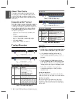
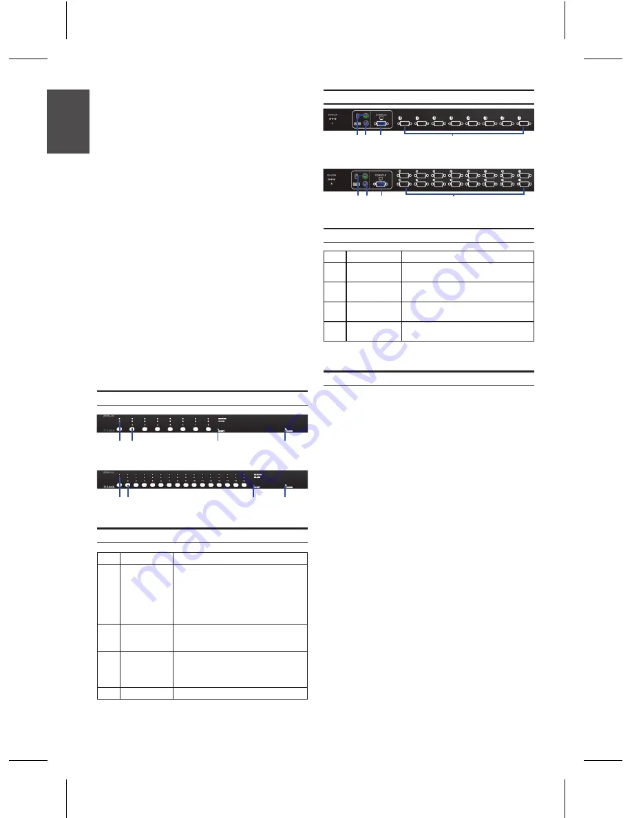
Front Panel

Item

Feature

Description

A

Status LEDs

Selected (Red):

A Red LED indicates that the 

corresponding PC is selected.

Online (Green):

A Green LED indicates that the 

corresponding PC is online.

B

Switch Button

Press the button corresponding to the 

computer you would like to select for 

control via console.

C

Reset Switch

Press the Reset switch when you would 

like to reset the device. The reset switch 

must be depressed using a thin object like 

the end of a paper clip, or a ball point pen.

D

Power LED

Indicates that the device is powered on.

Device Status LEDs and Buttons

Table 1. Front Panel Descriptions

Figure 1. DKVM-440 Front Panel

Figure 2. DKVM-450 Front Panel

D

B

A

C

D

B

A

C

Item

Feature

Description

A

PS/2 Console 

Mouse Port

Connects to the mouse cable of the 

controlling console PC

B

PS/2 Console 

Keyboard Port

Connects to the keyboard cable of the 

controlling console PC

C

Console Port 

(VGA)

Connects to the monitor cable of the 

controlling console PC

D

Power LED

Connects to the KVM combo cable of the 

target workstations

KVM Port Connections

Precautions:

•  Please turn off computers and attached devices 

when you begin installation of the KVM Switch. 

•  For computers with Keyboard Power On 

function, please unplug the power cords in 

advance. Otherwise, the switch may not work 

properly. 

•  If your computers run Windows 98, please 

connect the KVM switch to computers via PS/2 

ports. Windows 98 does not support first time 

installation through USB HID installation driver. 

•  Some older computers may require you 

to enable USB in BIOS to make the USB 

interface work.

Console connection:

Plug the keyboard, mouse and monitor into the 

console ports on the rear panel of the KVM Switch. 

System connection:

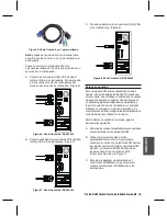
Use the custom combo cable to connect your 

computers. Refer to the figures and instruction 

shown below for information about connecting the 

KVM to PCs.

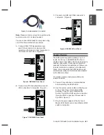
Figure 3. DKVM-440 Rear Panel

Table 1. Rear Panel Descriptions

Figure 4. DKVM-450 Rear Panel

Rear Panel

Installation

D

B

A

C

D

B

A

C

Summary of Contents for DKVM-440

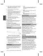
Page 1: ...te Quick Installation Guide Installationsanleitung Guide d installation Guía de instalación Guida di Installazione This document will guide you through the basic installation process for your new D Link KVM Switch DKVM 440 DKVM 450 Hardware Quick Installation Guide PS2 USB Combo KVM Switch ...

Page 2: ... the device is powered on Device Status LEDs and Buttons Table 1 Front Panel Descriptions Figure 1 DKVM 440 Front Panel Figure 2 DKVM 450 Front Panel D B A C D B A C Item Feature Description A PS 2 Console Mouse Port Connects to the mouse cable of the controlling console PC B PS 2 Console Keyboard Port Connects to the keyboard cable of the controlling console PC C Console Port VGA Connects to the ...

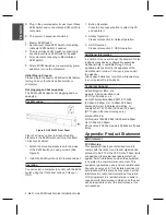
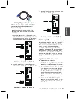
Page 3: ...s devices before installing the KVM Switch B Use the custom combo cable set See Figure 5 to connect one or more Slave KVM Switches to any PC port of Master KVM Switch The KVM to KVM must be connected through a PS 2 connection Please refer to Figure 6 Figure 7 C Plug in the power adapter of the first level Master KVM Switch and connect Master KVM switch to computers Note Please contact your reselle...

Page 4: ...ts to the KVM Switch unit for a standard 19 inch rack cabinet 1 Attach the mounting brackets onto the sides of the KVM Switch unit using screws See Figure 9 2 Install the KVM Switch unit into the rack cabinet Figure 9 DKVM 440 Front Panel D Plug in the power adapter for each level Slave KVM Switch and connect Slave KVM switch to computers E The power on sequence should be 1 Master KVM Switch 2 Sec...

Page 5: ...D Link KVM Switch Quick Installation Guide 5 NOTES ...

Page 6: ...stand wie einem Kugelschreiber gedrückt werden D LED Betriebsanzeige Zeigt an dass das Gerät eingeschaltet ist Gerätestatus LEDs und Tasten Vorsichtsmaßnahmen Schalten Sie die Computer und angeschlossenen Geräte vor dem Beginn der Installation des KVM Switch aus Für Computer mit der Funktion zum Einschalten über die Tastatur ziehen Sie die Netzstecker bitte vorab heraus Ansonsten könnte der Switch...

Page 7: ...ung von bis zu 64 256 4096 PCs von einer einzigen Konsole Für kaskadierte Einheiten ist keine spezielle Konfiguration erforderlich Ein Kaskadierungskonfiguration erweitert die Möglichkeiten des Systems und bietet die Auswahl von Computern die mit dem Master oder Slave verbunden sind Nach Herstellung der Verbindung konfigurieren sich die KVM Switches entsprechend als Master oder Slave automatisch s...

Page 8: ...acht wahrscheinlich Störungen die der Benutzer auf eigene Kosten beheben muss Betriebsoptionen Um mithilfe des KVM Switch einen Computer zur Steuerung und Verwaltung auszuwählen verwenden Sie die Tasten der Gerätevorderseite Hotkeys Tastenkominationen oder das OSD On Screen Display Abbildung 7 zeigt wie die Befestigungsklammern an das KVM Switch Gerät für einen Standard 19 Zoll Schaltschrank angeb...

Page 9: ...D Link KVM Switch Quick Installation Guide 9 NOTES ...

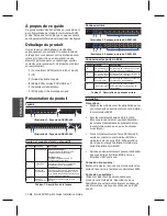
Page 10: ...oyants d état du dispositif Tableau 1 Description de la façade Précautions Éteignez les ordinateurs et les périphériques qui y sont connectés avant de commencer à installer le commutateur KVM Pour les ordinateurs équipés de la fonction Mise sous tension clavier veuillez débrancher les cordons d alimentation au préalable Sinon le commutateur risque de ne pas fonctionner correctement Si vos ordinate...

Page 11: ...teur KVM prend en charge les cascades jusqu à 3 niveaux Contrôlez jusqu à 64 256 4096 PC depuis une seule console Les unités en cascade ne nécessitent aucune configuration particulière La configuration en cascade étend les fonctionnalités du système et vous permet de sélectionner les ordinateurs connectés en maître ou en esclave Une fois connectés les commutateurs KVM se configurent automatiquemen...

Page 12: ...essaires pour éliminer à ses frais la cause des perturbations Montage sur rack Fonctionnement Vous pouvez sélectionner un ordinateur qui contrôlera le commutateur KVM à l aide des boutons de la façade des touches ou de l OSD L illustration 7 indique comment fixer les supports de montage sur le commutateur KVM pour obtenir une armoire à racks standard de 19 pouces 1 Fixer les supports de montage su...

Page 13: ...D Link KVM Switch Quick Installation Guide 13 NOTES ...

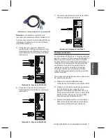
Page 14: ...icadores LED y botones de estado del dispositivo Precauciones Apague los ordenadores y los dispositivos conectados al comenzar la instalación del conmutador KVM Para los ordenadores con función de activación por teclado desenchufe antes los cables de alimentación En caso contrario puede que el conmutador no funcione correctamente Si sus ordenadores funcionan bajo Windows 98 conecte el conmutador K...

Page 15: ...e cascadas de hasta 3 niveles Controle hasta 64 256 4096 PC desde una única consola Las unidades en cascada no necesitan ninguna configuración especial Una configuración en cascada amplía las capacidades del sistema y le permite seleccionar los ordenadores conectados al Maestro o el Esclavo Una vez conectados los conmutadores KVM se configurarán automáticamente correctamente como Maestro o Esclavo...

Page 16: ... desee controlar con el conmutador KVM utilizando los botones teclas de función u OSD del panel frontal La Figura 7 muestra el modo de acoplar los soportes de montaje a la unidad del conmutador KVM para un bastidor de estantes estándar de 19 pulgadas 1 Acople los soportes de montaje a los laterales de la unidad del conmutador KVM utilizando tornillos Consulte la Figura 9 2 Instale la unidad del co...

Page 17: ...D Link KVM Switch Quick Installation Guide 17 D Link KVM Switch Quick Installation Guide 17 NOTES ...

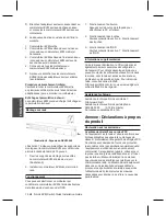
Page 18: ...i collegati prima di iniziare l installazione dello switch KVM Per i computer dotati della funzione di accensione tastiera scollegare prima i cavi di alimentazione In caso contrario lo switch potrebbe non funzionare correttamente Se nei computer in uso è in esecuzione Windows 98 collegare lo switch KVM ai computer tramite le porte PS 2 Windows 98 non supporta l esecuzione della prima installazione...

Page 19: ... in cascata Lo switch KVM supporta fino a tre livelli di collegamento in cascata e consente quindi di controllare fino a 64 256 4096 PC da un unica console Per le unità collegate in cascata non è richiesta alcuna configurazione speciale Una configurazione in cascata consente di espandere le funzionalità del sistema e di selezionare i computer collegati allo switch master o slave Dopo il collegamen...

Page 20: ...ali interferenze Montaggio in rack Funzionamento Per selezionare un computer da controllare tramite lo switch KVM utilizzare i pulsanti del pannello frontale i tasti di scelta rapida o i menu OSD On Screen Display Nella figura 7 viene spiegato come fissare le staffe di montaggio allo switch KVM per un armadio rack standard da 19 1 Utilizzare le viti per fissare le staffe di montaggio sui lati dell...

Page 21: ...D Link KVM Switch Quick Installation Guide 21 NOTES ...

Page 22: ...22 D Link KVM Switch Quick Installation Guide BAHASA INDONESIA NOTES ...

Page 23: ...D Link KVM Switch Quick Installation Guide 23 NOTES ...

Page 24: ...Ver 1 00 E 2010 05 03 2R45284LA ...

Reviews: