E
N
G
L
IS
H
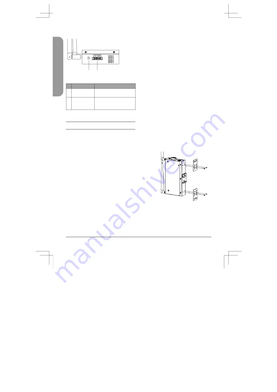
Side Panel Features
1
2
Figure 2: Left Panel Interface Connectors
#
Connector
Description
1
Switch Ground
This is used to connect
the device to ground.
This is used to connect the
2 Terminal Block
device to external power
sources
and an alarm relay.
Table 2: Side Panel Features
Hardware Installation
Before You Begin
Observe the following precautions to help
prevent shutdowns, equipment failures,
and personal injury:
•
Install the DIS-2650AP in a cool and
dry place.
•
Install the DIS-2650AP in a site free
from strong electromagnetic sources,
vibration, dust, excessive moisture,
and direct sunlight.
•
Place antennas in an unobstructed area
with a clear signal. Avoid metal boxes,
brick walls, and other dense materials.
•
Visually inspect the power connector
and make sure that it is fully secure.
•
Do not stack any devices on top of
the DIS-2650AP.
Attach the External Antennas
The DIS-2650AP requires two external antennas to
function correctly. The included antennas are
interchangeable
1. Attach the two included antennas to
the RP-SMA connectors on the side
of the DIS-2650AP. Turn clockwise
to fasten the antennas.
2.
Arrange the antennas so that they’re
pointing upwards and in a configuration
to receive optimal signals.
Mounting the Device on a Wall
The DIS-2650AP can be installed on a
solid surface by using the included wall
mounting plates attached to the back of
the device. Use the following instructions
to install the DIS-2650AP on a wall:
1.
Align the cross-section of the mounting
plates with the openings on the back of
the device. Secure the plates with the
included mounting screws.
Figure 3: Attaching Mounting Plates
2.
Remove the DIN rail mounting clip from
the back of the device (if present).
2
DIS-2650AP Quick Installation Guide
Summary of Contents for DIS-2650AP
Page 2: ...Contents English 1 ...
Page 12: ...Notes ...
Page 13: ...Notes ...
Page 14: ...Notes ...
Page 15: ...Notes ...
Page 16: ...Ver 1 00 WW _130x183 2020 12 07 5300 00007836 01W ...


