background image

DGS-3224TGR Gigabit Ethernet Switch User’s Guide 

66 

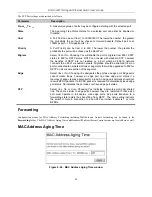
Set the MAC Address Aging Time and click the 

Apply

 button. MAC Address Aging Time specifies the length of time a 

learned MAC Address will remain in the forwarding table without being accessed (that is, how long a learned MAC 
Address is allowed to remain idle). The Aging Time can be set to any value between 10


and 1,000,000 seconds.   


NOTE:  A very long Aging Time can result with the out-of-date Dynamic Entries 
that may cause incorrect packet filtering/forwarding decisions. A very short 
aging time may cause entries to be aged out to soon, resulting in a high 
percentage of received packets whose source addresses cannot be found in 
the address table, in which case the switch will broadcast the packet to all 
ports, negating many of the benefits of having a switch. 

Unicast MAC Address Settings 


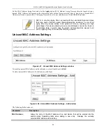
Figure 6- 47.  Unicast MAC Address Settings window 

To modify a unicast MAC address on the table above, select it and then click 

Edit

To add a unicast MAC address to the table above, click 

New


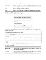
Figure 6- 48.  Unicast MAC Address Settings – Add window 

The following fields can be set: 

Parameter 

            Description 

MAC Address 

Allows the entry of the MAC address of an end station that will be entered into the 
switch’s static forwarding table when adding a new entry.  Displays the currently 
selected MAC address when editing. 

Summary of Contents for DGS-3224TGR - Switch

Page 1: ...D Link DGS 3224TGR Managed 24 Port Gigabit Ethernet Switch User s Guide...

Page 2: ...in accordance with this user s guide may cause harmful interference to radio communications Operation of this equipment in a residential area is likely to cause harmful interference in which case the...

Page 3: ...er Failure 6 External Redundant Power System 6 Identifying External Components 7 Front Panel 7 Rear Panel 7 Side Panels 8 LED Indicators 8 Connecting The Switch 9 Switch to End Node 9 Switch to Hub or...

Page 4: ...agement 27 Introduction 27 Getting Started 27 Basic Setup 31 Switch Information 31 Basic Switch Setup 33 Serial Port Settings 34 Port Configurations 35 Port Description Settings 37 Traffic Segmentatio...

Page 5: ...egation 91 Link Aggregation Algorithm 91 Link Aggregation Group 91 LACP Port Settings 93 802 1X 95 802 1X State 95 802 1X Auth Mode Settings 96 802 1X Port Settings 96 802 1X Port Auth State 100 802 1...

Page 6: ...figuration 120 SSL V3 Configuration 121 TLS V1 Configuration 122 Single IP Management 123 SIM Settings 123 SIM Using the Web Interface 124 Topology 126 Tool Tips 128 Right Click 129 Commander Switch I...

Page 7: ...etwork Management Tells how to manage the Switch through an Internet browser Chapter 7 D Link s Single IP Management An introduction to the new D Link switch management feature used to manage multiple...

Page 8: ...DGS 3224TGR Gigabit Ethernet Switch User s Guide viii CAUTION A CAUTION indicates a potential for property damage personal injury or death...

Page 9: ...vironment If the system gets wet see the appropriate section in your troubleshooting guide or contact your trained service provider Do not push any objects into the openings of your system Doing so ca...

Page 10: ...cable to the power supply Unplug the power cable before removing the power supply If the system has multiple sources of power disconnect power from the system by unplugging all power cables from the p...

Page 11: ...er airflow is provided to components in the rack Do not step on or stand on any component when servicing other components in a rack NOTE A qualified electrician must perform all connections to DC powe...

Page 12: ...m its shipping carton do not remove the component from the antistatic packing material until you are ready to install the component in your system Just before unwrapping the antistatic packaging be su...

Page 13: ...PC using a terminal emulation program Performance Features Store and forward switching scheme Switching fabric 48Gbps Max Forwarding Rate 35 7 million packets per second High speed data forwarding rat...

Page 14: ...RFC 1493 MIB II RFC 1213 802 1P Q MIB RFC 2674 Interface MIB RFC 2233 Ethernet like MIB RFC 1643 Mini RMON MIB RFC 1757 4 groups The RMON specification defines the counters for the receive functions o...

Page 15: ...cords A printed QIG A printed User s Guide D View 5 1 demo CD ROM This User s Guide with Registration Card on CD ROM If any item is found missing or damaged please contact your local D Link reseller...

Page 16: ...between the device and the objects around it Figure 2 1 Installing rubber feet for desktop installation Rack Installation The DGS 3224TGR can be mounted in an EIA standard sized 19 inch rack which can...

Page 17: ...d in the LED indicators should respond as follows All LED indicators except console will momentarily blink This blinking of the LEDs indicates a reset of the system The console LED indicator will blin...

Page 18: ...itch When power is resumed plug the switch back in External Redundant Power System The switch supports an external redundant power system Figure 2 3 DPS 300 in DPS 900 with DGS 3224TGR NOTE See the DP...

Page 19: ...r 10 100 1000 connections to a backbone end stations and servers Four mini GBIC combo ports to connect fiber optic media to another switch server or network backbone Rear Panel The rear panel of the s...

Page 20: ...g with an explanation of each indicator Figure 3 4 LED indicators Power This indicator on the front panel lights solid green when the system is powered up and remains dark when the system is not power...

Page 21: ...nd most routers An end node can be connected to the switch via a Category 3 4 5 or 5e UTP STP cable for optimal performance Category 5e is recommended The end node should be connected to any of the po...

Page 22: ...nected to the switch via a two pair Category 3 4 5 or 5e UTP STP cable A 100BASE TX hub or switch can be connected to the switch via a two pair Category 5 or 5e UTP STP cable A 1000BASE T switch can b...

Page 23: ...the console program built in to the switch see the DGS 3224TGR Command Line Interface Reference manual A network administrator can manage control and monitor the switch from the console program The D...

Page 24: ...Alternatively you can enter the commands config ipif System ipaddress xxx xxx xxx xxx z Where the x s represent the IP address to be assigned to the IP interface named System and the z represents the...

Page 25: ...nly constants are the number of port and type of ports Examples of read only variables are the statistics counters such as the number of errors that have occurred or how many kilobytes of data have be...

Page 26: ...g table entries that are out of date or no longer exist This may cause incorrect packet forwarding decisions by the Switch If the Aging Time is too short however many entries may be aged out too soon...

Page 27: ...e a stable topology in the same way Every segment will have a single path to the root bridge All bridges listen for BPDU packets However BPDU packets are sent more frequently with every Hello packet B...

Page 28: ...broadcast packets are forwarded to only members of the VLAN on which the broadcast was initiated Note VLANs on the DGS 3224TGR No matter what basis is used to uniquely identify end nodes and assign th...

Page 29: ...he forwarding of untagged packets to the VLAN the receiving port is a member of The main characteristics of IEEE 802 1Q are as follows Assigns packets to VLANs by filtering Assumes the presence of a s...

Page 30: ...ey can be carried across Ethernet backbones and twelve bits of VLAN ID VID The three bits of user priority are used by 802 1p The VID is the VLAN identifier and is used by the 802 1Q standard Because...

Page 31: ...aware and tag unaware network devices can coexist on the same network A switch port can have only one PVID but can have as many VIDs as the switch has memory in its VLAN table to store them Because s...

Page 32: ...easure for authorizing and authenticating users to gain access to various wired or wireless devices on a specified Local Area Network by using a Client and Server based access control model This is ac...

Page 33: ...uthentication Server Authenticator The Authenticator the Switch is an intermediary between the Authentication Server and the Client The Authenticator servers two purposes when utilizing 802 1x The fir...

Page 34: ...ons must be running software that is compliant with the 802 1x protocol For users running Windows XP that software is included within the operating system All other users are required to attain 802 1x...

Page 35: ...rol used on the Switch which are 1 Port Based Access Control This method requires only one user to be authenticated per port by a remote RADIUS server to allow the remaining users on the same port acc...

Page 36: ...onnected Client has successfully been authenticated the Port then becomes Authorized and all subsequent traffic on the Port is not subject to access control restriction until an event occurs that caus...

Page 37: ...Dynamic Host Configuration Protocol DHCP can reduce the administrative burden of assigning and maintaining IP address information DHCP provides reliable and simple TCP IP network configuration ensures...

Page 38: ...es more than one network adapter to connect to multiple networks this protocol is followed for each adapter that the user wants to configure for TCP IP Multi homed systems are selectively configured f...

Page 39: ...t is necessary to download Java Runtime Environment 1 4 2 to display the Topology windows located in the Single IP Management folder Getting Started The first step in getting started in using Web base...

Page 40: ...individual port on this display will connect you to the Port Configurations window see Basic Setup Port Configurations for a detailed description The panel on the left hand side contains the main menu...

Page 41: ...DGS 3224TGR Gigabit Ethernet Switch User s Guide 29...

Page 42: ...These are the major categories for switch management If the sub menus for each main category do not appear click on the small square hyperlink to the left of the folder icon The switch management feat...

Page 43: ...c Switch Setup Serial Port Settings Port Configurations Port Description Settings Traffic Segmentation Table User Accounts Network Management Switch Utilities Network Monitoring Factory Reset Save Cha...

Page 44: ...sical location of the switch Contact Name of the person to contact should there be any problems or questions with the system You may also want to include a phone number or extension Spanning Tree This...

Page 45: ...the switch If you enable BOOTP you do not need to configure any IP parameters because a BOOTP server automatically assigns IP configuration parameters to the switch If you enable DHCP a Dynamic Host...

Page 46: ...tion of the switch Contact Name of the person to contact should there be any problems or questions with the system You may also want to include a phone number or extension State This allows you to ena...

Page 47: ...it Ethernet Switch User s Guide 35 Port Configurations Figure 6 4 first Port Configurations window To make changes to port configurations select a port and click Edit The following Port Configurations...

Page 48: ...00M Full_M is selected on one end of the link pair then 1000M Full_S must be selected on the other end of your D Link switch and vice versa For 1000M connections to switches that do not possess master...

Page 49: ...rious ports on the Switch To assign names to various ports 1 Click Port Description Settings on the Basic Setup menu 2 Use the From and To pull down menu to choose a port or range of ports to describe...

Page 50: ...ature prevents the traffic of a specific port on the switch from being transferred to other ports on the switch When an incoming packet from a specific port is received it is only forwarded to the por...

Page 51: ...following windows Figure 6 9 User Accounts window The information on the window is described as follows The following fields can be set Parameter Description User Name Displays all current users for t...

Page 52: ...ription User Name Enter a user name in this field New Password Enter the desired new password in this field Confirm New Password Enter the new password a second time Access Level Displays the current...

Page 53: ...The three versions of SNMP vary in the level of security provided between the management station and the network device SNMP settings are configured using the menus located on the SNMP V3 folder of t...

Page 54: ...Subtree for the view The OID identifies an object tree MIB tree that will be included or excluded from access by an SNMP manager View Type Select Included to include this object in the list of objects...

Page 55: ...SNMP Host Table window To delete an existing entry click the selection button in the right hand column that corresponds to the port you want to remove and then click Delete To create a new entry clic...

Page 56: ...MP version 3 will be used with an Auth NoPriv security level V3 Auth Priv To specify that the SNMP version 3 will be used with an Auth Priv security level Community String SNMPv3 User Name Type in the...

Page 57: ...es that SNMP version 1 will be used SNMPv2 Specifies that SNMP version 2c will be used The SNMP v2c supports both centralized and distributed network management strategies It includes improvements in...

Page 58: ...e the new Engine ID in the space provided and click the Apply button SNMP User Table Use the SNMP User Table to create a new SNMP user and add the user to an existing SNMP group or to a newly created...

Page 59: ...P version 2 will be used V3 To specify that the SNMP version 3 will be used If Encryption V3 only is checked configure also Auth Protocol In the space provided type an alphanumeric sting of between 8...

Page 60: ...tion IP Addresses window Switch Utilities TFTP Services Trivial File Transfer Protocol TFTP services allow the switch firmware to be upgraded by downloading a new firmware file from a TFTP server to t...

Page 61: ...Enter the IP address of the TFTP Server in the Server IP Address field and the complete path and file name of the firmware file for the switch in the Path Filename field Click Download to initiate the...

Page 62: ...r the information described below to upload Switch configuration settings to a TFTP server Parameter Description Server IP Address The IP address of the TFTP server Path File Name The full file name i...

Page 63: ...le on the TFTP server Ping Test The switch is able to test the connection with another network device using Ping Figure 6 28 Ping Test window Enter the IP address of the network device to be Pinged in...

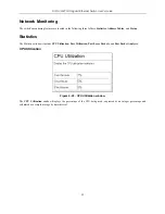
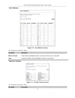
Page 64: ...Address Tables and Status Statistics The Statistics windows include CPU Utilization Port Utilization Port Error Packets and Port Packet Analysis CPU Utilization Figure 6 29 CPU Utilization window The...

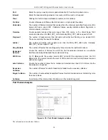
Page 65: ...described as follows Parameter Description Refresh Interval Select the desired setting between 2 seconds and 60 second or Suspend Clear Clicking this button clears all statistics counters on this win...

Page 66: ...er The number of frames with lengths more than the MAX_PKT_LEN bytes Internally MAX_PKT_LEN is equal to 1522 Drop Packets The number of frames that are dropped by this port since the last Switch reboo...

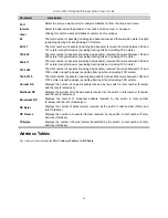
Page 67: ...ncluding FCS octets 512 1023 The total number of packets including bad packets received that were between 512 and 1023 octets in length inclusive excluding framing bits but including FCS octets 1024 1...

Page 68: ...s Table Figure 6 33 MAC Address Table window The information is described as follows Parameter Description Browse Click this button to initiate the desired method for viewing MAC addresses Clear Click...

Page 69: ...mic from the pull down menu Click the Find button to initiate the search for the ARP Table Clicking the Clear Table button to clear all statistics counters on this window Status The Status windows inc...

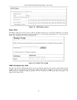
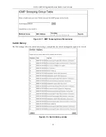
Page 70: ...by S A router port that is dynamically configured by the switch is designated by D Figure 6 36 Router Ports window IGMP Snooping Group Table This allows the switch s IGMP Snooping table to be viewed I...

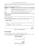
Page 71: ...et Switch User s Guide 59 Figure 6 37 IGMP Snooping Group Table window Switch History The Web manager allows the switch s history log as compiled by the switch s management agent to be viewed Figure 6...

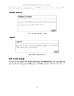
Page 72: ...arted Log Text Displays text describing the event that triggered the history log entry Factory Reset The following window allows you to Reset Reset Config or Reset System See the on screen instruction...

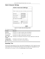
Page 73: ...s rebooted Restart System Figure 6 41 Restart System window Logout Figure 6 42 Logout window Advanced Setup This category includes Switch Advanced Settings Spanning Tree Forwarding Configure QOS Acces...

Page 74: ...nfigure the timeout value of an entry maintained in the ARP table Year Month Date This allows you to set the year month and date Hour Minute Secon d This allows you to set the hour minute and second S...

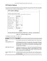
Page 75: ...econds At the end of the Maximum Age if a BPDU has still not been received from the Root Bridge your switch will start sending its own BPDU to all other switches for permission to become the Root Brid...

Page 76: ...function with legacy equipment TX Hold Count 1 10 3 This is the maximum number of Hello packets transmitted per interval The count can be specified from 1 to 10 The default value is 3 Forwarding BPDU...

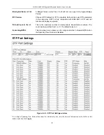
Page 77: ...tations or segments that will be upgraded to 802 1w RSTP on all or some portion of the segment Edge Select Yes or No Choosing Yes designates the port as an edge port Edge ports cannot create loops how...

Page 78: ...d out to soon resulting in a high percentage of received packets whose source addresses cannot be found in the address table in which case the switch will broadcast the packet to all ports negating ma...

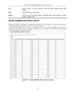
Page 79: ...orwarding Table These addresses will never age out Figure 6 49 Multicast MAC Address Settings window Click New to add multicast MAC addresses to the table above To make changes to an existing entry se...

Page 80: ...ol Broadcast and multicast storms consist of broadcast or multicast packets that flood and or are looped on a network causing noticeable performance degradation and in extreme cases network failure Th...

Page 81: ...e Multicast Storm Mode is Enabled or Disabled using a pull down menu When the Multicast Storm Mode is Enabled and a port contained within the corresponding port group receives more multicast packets t...

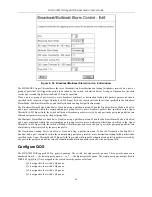
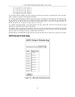
Page 82: ...n the following sequence A1 B1 C1 D1 E1 F1 G1 H1 A2 B2 C2 D2 E2 F2 G2 A3 B3 C3 D3 E3 F3 A4 B4 C4 D4 E4 A5 B5 C5 D5 A6 B6 C6 A7 B7 A8 A1 B1 C1 D1 E1 F1 G1 H1 For weighted round robin queuing if each Co...

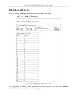
Page 83: ...s the assignment of a default 802 1p priority to each port on the switch Figure 6 54 802 1p Default Priority window This window allows you to assign a default 802 1p priority to any given port on the...

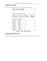
Page 84: ...he DGS 3224TGR allows the assignment of a User Priority to each of the 802 1p priorities Figure 6 55 802 1p User Priority window Bandwidth Control Table The bandwidth control settings are used to plac...

Page 85: ...new window opens Figure 6 57 Bandwidth Control Table Edit window To limit either the Rx or Tx rates deselect the No Limit check box and enter the desired rate Rates can be expressed using whole number...

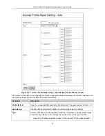
Page 86: ...cess Profile Mask Setting window click the New button This will open an Access Profile Mask Setting Add window as shown below There are three Access Profile Mask Setting Add windows one for Ethernet o...

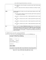
Page 87: ...he VLAN identifier of each packet header and use this as the full or partial criterion for forwarding Source MAC Source MAC Mask Enter a MAC address mask for the source MAC address Destination MAC Des...

Page 88: ...Select profile based on Ethernet MAC Address IP address or packet content mask This will change the window according to the requirements for the type of profile IP instructs the Switch to examine the...

Page 89: ...s are parts of a packet that determine what to do with the packet The user may filter packets by filtering certain flag bits within the packets by checking the boxes corresponding to the flag bits of...

Page 90: ...gure the Packet Content Mask Parameter Description Profile ID 1 8 Type in a unique identifier number for this profile set This value can be set from 1 8 Auto Assign Checking this box instructs the Swi...

Page 91: ...er a value in hex form to mask the packet from byte 48 to byte 63 value 64 79 Enter a value in hex form to mask the packet from byte 64 to byte 79 Port The user may set the Access Profile Mask Setting...

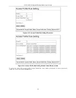
Page 92: ...ss Profile Rule Setting IP window Figure 6 64 Access Profile Rule Setting Packet Content Mask window To create a new rule set for an access profile click the New button A new window is displayed To re...

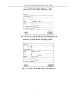
Page 93: ...DGS 3224TGR Gigabit Ethernet Switch User s Guide 81 Figure 6 65 Access Profile Rule Setting Add Ethernet window Figure 6 66 Access Profile Rule Setting Add IP window...

Page 94: ...le Setting Add Package Content Mask window Configure the following Access Profile Rule Settings Parameter Description Profile ID This is the identifier number for this profile set Access Rule ID Type...

Page 95: ...adjacent field Protocol Selecting this option instructs the Switch to examine the protocol type value in each frame s header You must then specify what protocol s to include according to the followin...

Page 96: ...DGS 3224TGR Gigabit Ethernet Switch User s Guide 84 Figure 6 68 Port Security Settings window Click Edit to open the following window...

Page 97: ...ically learned MAC addresses in the forwarding table Mode DeleteOnReset Select DeleteOnTimeout to clear dynamic entries for the ports on timeout of the Forwarding Data Base FDB When DeleteOnReset is s...

Page 98: ...on will be duplicated and sent for capture and network analysis This is the port where a network analyzer would be attached to capture packets duplicated from the source port Up to 25 entries can be m...

Page 99: ...s This section includes Asymmetric VLAN State Switch GVRP 802 1Q VLANs and IEEE 802 1Q Settings Asymmetric VLAN State Figure 6 73 Asymmetric VLAN State window To set Asymmetric VLANs on the DGS 3224TG...

Page 100: ...6 75 802 1Q VLANs window To delete an existing 802 1Q VLAN click the corresponding click box to the left of the VLAN you want to delete from the switch and then click the Delete button To create a ne...

Page 101: ...o be specified as member of a VLAN Non member Allows an individual port to be specified as a non VLAN member Tagged Untagged Allows an individual port to be specified as Tagged or Untagged A check in...

Page 102: ...ID in the packet before forwarding the packet GARP VLAN Registration Protocol GVRP is a Generic Attribute Registration Protocol GARP application that provides 802 1Q compliant VLAN pruning and dynamic...

Page 103: ...information on the algorithm settings is described as follows Parameter Description MAC source Indicates that the switch should examine the MAC source address MAC destination Indicates that the switc...

Page 104: ...lancing is automatically applied to the ports in the aggregated group and a link failure within the group causes the network traffic to be directed to the remaining links in the group The Spanning Tre...

Page 105: ...passive and active modes Both the passive and active modes allow LACP to negotiate between LAN ports to determine if they can form a link aggregation Passive LACP mode that places a port into a passiv...

Page 106: ...DGS 3224TGR Gigabit Ethernet Switch User s Guide 94 Figure 6 82 LACP Port Settings window To edit a LACP Port Table entry select it and then click Edit...

Page 107: ...a user or network device must meet before allowing that port to forward or receive frames IEEE 802 1X operation must be enabled on the switch before it will function This is done using the 802 1X Stat...

Page 108: ...85 802 1X Auth Mode Settings window The following fields are described below Parameter Description 802 1X Auth Mode Set the 802 1X Auth Mode to either port based or mac based 802 1X Port Settings Exi...

Page 109: ...hernet Switch User s Guide 97 Figure 6 86 802 1X Port Settings window Click the selection button on the far left that corresponds to the port you want to configure and click the Edit button The follow...

Page 110: ...e The port is not controlled by the 802 1x functions AdminCrlDir From the pull down menu select whether a controlled Port that is unauthorized will exert control over communication in both receiving a...

Page 111: ...start of a new authentication attempt TxPeriod 1 65535 Select the time to wait for a response from a supplicant user to send EAP Request Identity packets SuppTimeout 1 65535 Select the time to wait f...

Page 112: ...DGS 3224TGR Gigabit Ethernet Switch User s Guide 100 802 1X Port Auth State Figure 6 88 802 1x Port Auth State Port based window...

Page 113: ...nticated Aborting Held ForceAuth ForceUnauth and N A Backend State The Backend Authentication State will display one of the following Request Response Success Fail Timeout Idle Initialize and N A Port...

Page 114: ...is the only parameter to be configured RADIUS Server Settings Use this window to configure the settings the switch will use to communicate with a RADIUS server Figure 6 92 RADIUS Server Settings windo...

Page 115: ...and the switch Up to 32 characters can be used AuthPortNumber Type the UDP port number for authentication requests The default is 1812 AcctPortNumber Type the UDP port number for accounting requests i...

Page 116: ...DGS 3224TGR Gigabit Ethernet Switch User s Guide 104 802 1X Auth Diagnostics Figure 6 96 802 1X Auth Diagnostics Port based window Figure 6 97 802 1X Auth Diagnostics MAC based window...

Page 117: ...DGS 3224TGR Gigabit Ethernet Switch User s Guide 105 802 1X Auth Statistics Figure 6 98 802 1X Auth Statistics Port based window Figure 6 99 802 1X Auth Statistics MAC based window...

Page 118: ...3224TGR Gigabit Ethernet Switch User s Guide 106 802 1X Auth Session Statistics Figure 6 100 802 1X Auth Session Statistics Port based window Figure 6 101 802 1X Auth Session Statistics MAC based win...

Page 119: ...TACACS and XTACACS TACACS TACACS XTACACS is implemented in the switch s software to allow centralized control over access to servers Authentication can also be provided for administrative tasks on th...

Page 120: ...S Server Settings window To add an entry to this table click New To modify an entry select it and then click Edit Figure 6 106 TACACS Server Settings Add window To modify an entry on the TACACS Server...

Page 121: ...ide 109 TACACS Group Figure 6 108 TACACS Group window To add an entry to this table click New To remove an entry select it and then click Delete Figure 6 109 TACACS Group Add window TACACS Group Setti...

Page 122: ...TACACS Group Settings Add window TACACS Method List Figure 6 112 TACACS Method List window To add an entry to this table click New To modify an entry on this table select it and then click Edit To re...

Page 123: ...this window and will have to enter an authentication password Possible authentication methods for this function include TACACS XTACACS TACACS RADIUS user defined server groups local enable local accou...

Page 124: ...e System Log Server System Log State Figure 6 117 System Log State window To enable the System Log Server settings you have chosen on the System Log Server windows select Enabled and click the Apply b...

Page 125: ...he IP address of the Syslog server receiving the message Severity Select the level of message sent select Warning Informational or All Facility Some of the operating system daemons and processes have...

Page 126: ...lock daemon 10 security authorization messages 11 FTP daemon 12 NTP subsystem 13 log audit 14 log alert 15 clock daemon 16 local use 0 local0 17 local use 1 local1 18 local use 2 local2 19 local use 3...

Page 127: ...MP snooping configuration settings in the window above The Query Interval 1 65535 can be set between 1 and 65 535 seconds and determines the time between IGMP queries The Max Response 1 25 value allow...

Page 128: ...ndow SSH Management SSH is the abbreviation of Secure Shell which is a program allowing secure remote login and secure network services over an insecure network It allows you to securely login to remo...

Page 129: ...ms The information is described as follows Parameter Description Maximum Simultaneous Sessions 1 8 Specify how many sessions at most the server program will handle simultaneously Connection Timeout 12...

Page 130: ...rted by server 3DES Use 3DES encryption Blowfish Use Blowfish encryption Data Integrity Specify the desired MAC algorithm to use for the data integrity verification SHA 1 Use the hmac sha1 MAC MD5 Use...

Page 131: ...encryption of the current block The Switch supports the 3DES EDE encryption code defined by the Data Encryption Standard DES to create the encrypted text 3 Hash Algorithm This part of the ciphersuite...

Page 132: ...ion of listed ciphersuites on the Switch A ciphersuite is a security string that determines the exact cryptographic parameters specific encryption algorithms and key sizes to be used for an authentica...

Page 133: ...RC4_40_MD5 This ciphersuite combines the RSA Export key exchange and stream cipher RC4 encryption with 40 bit keys Use the pull down menu to enable or disable this ciphersuite This field is Enabled by...

Page 134: ...iguration Figure 6 132 TLS V1 Configuration window To set up TLS version 1 on the Switch toggle to Enabled and click Apply Parameter Description TLS v1 State Use the pull down menu to enable or disabl...

Page 135: ...The Commander Switch CS which is the master Switch of the group Member Switch MS which is a Switch that is recognized by the CS a member of a SIM group and a Candidate Switch CaS which is a Switch th...

Page 136: ...ure a CaS to become a CS The CaS can be configured through the CS to become a MS After configuring one Switch to operate as the CS of a SIM group additional DGS 3224TGRSwitches may join the group eith...

Page 137: ...e of the Switch The two choices are Candidate A Candidate Switch CaS is not the member of a SIM group but is connected to a Commander Switch This is the default setting for the SIM role of the DGS 322...

Page 138: ...ow holds the following information under the Data tab Parameter Description Device Name This field will display the Device Name of the Switches in the SIM group configured by the user If no Device Nam...

Page 139: ...Group are connected to other groups and devices Possible icons in this screen are as follows Icon Description Group Layer 2 commander Switch Layer 3 commander Switch Commander Switch of other group La...

Page 140: ...etting the mouse cursor over a specific device in the topology window tool tip will display the same information about a specific device as the Tree view does See the window below for an example Figur...

Page 141: ...unctions depending on the role of the Switch in the SIM group and the icon associated with it Group Icon Figure 7 7 Right Clicking a Group Icon The following options may appear for the user to configu...

Page 142: ...Switch Icon Figure 7 9 Right Clicking a Commander Icon The following options may appear for the user to configure Collapse to collapse the group that will be represented by a single icon Expand to ex...

Page 143: ...The following options may appear for the user to configure Collapse to collapse the group that will be represented by a single icon Expand to expand the SIM group in detail Remove from group remove a...

Page 144: ...sented by a single icon Expand to expand the SIM group in detail Add to group add a candidate to a group Clicking this option will reveal the following dialog box for the user to enter a password for...

Page 145: ...isplays the number of the physical port on the MS or CaS that the CS is connected to The CS will have no entry in this field Local Port No Displays the number of the physical port on the CS that the M...

Page 146: ...7 17 Input password window Remove from Group remove an MS from the group Device Configure will open the web manager for the specific device View Refresh update the views with the latest status Topolo...

Page 147: ...th Filename of the firmware Click Download to initiate the file transfer Configuration Backup Restore Figure 7 19 Configuration Backup Restore window This window is used to upgrade configuration files...

Page 148: ...eues per port Forwarding Table Age Time Max age 10 1000000 seconds Default 300 Physical and Environmental AC inputs 100 240 VAC 50 60 Hz internal universal power supply Power Consumption 60 watts maxi...

Page 149: ...000BASE T 1000BASE LX 1000BASE SX 1000BASE LHX 1000BASE ZX Mini GBIC UTP Category 3 4 5 100 meters max EIA TIA 568 150 ohm STP 100 meters max UTP Cat 5 100 meters max EIA TIA 568 150 ohm STP 100 meter...

Page 150: ...Single mode fiber module 10km DEM 311GT SFP Transceiver for 1000BASE SX Multi mode fiber module 550m DEM 314GT SFP Transceiver for 1000BASE LHX Single mode fiber module 40km Mini GBIC DEM 315GT SFP T...

Page 151: ...between network segments BOOTP The BOOTP protocol allows you to automatically map an IP address to a given MAC address each time a device is started In addition the protocol can assign the subnet mask...

Page 152: ...Network Management Protocol SNMP to contain attributes of their managed systems The Switch contains its own internal MIB multicast Single packets copied to a specific subset of network addresses Thes...

Page 153: ...File Transfer Protocol Allows you to transfer files such as software upgrades from a remote device using your switch s local management capabilities UDP User Datagram Protocol An Internet standard pro...

Page 154: ...Netzkabel oder Netzstecker sint besch digt b Fl ssigkeit ist in das Ger t eingedrungen c Das Ger t war Feuchtigkeit ausgesetzt d Wenn das Ger t nicht der Bedienungsanleitung ensprechend funktioniert...

Page 155: ...insurance prepaid D Link shall never be responsible for any software firmware information or memory data of Purchaser contained in stored on or integrated with any product returned to D Link pursuant...

Page 156: ...rance or liquidation sale or other sales in which D Link the sellers or the liquidators expressly disclaim their warranty obligation pertaining to the product and in that case the product is being sol...

Page 157: ...SS WRITTEN WARRANTIES AND REMEDIES RE EXCLUSIVE AND ARE IN LIEU OF ANY OTHER WARRANTIES OR REMEDIES EXPRESS IMPLIED OR STATUTORY A Governing Law This Limited Warranty shall be governed by the laws of...

Page 158: ...egistration Register online your D Link product at http support dlink com register Product registration is entirely voluntary and failure to complete or return this form will not diminish your warrant...

Page 159: ...ng questions help us to support your product 1 Where and how will the product primarily be used oHome oOffice oTravel oCompany Business oHome Business oPersonal Use 2 How many employees work at instal...

Page 160: ......

Reviews: