background image

4  Configuration


D-Link Web Smart Switch User Manual


7

7

9

9


User Define:

 Check the box and input the power budget (from 1 to 30W) to manually assign an upper limit of 

port power budget on designated port(s). 


Click 

Apply

 to make the configurations take effects or click 

Refresh

 to redisplay the table. 


Note:  For  the  PoE  Port  Settings  table,  if  the 
classification was shown as 

“Legacy PD”, it will be 

classified to non-AF PD or Legacy PD. 


SNMP > SNMP > SNMP Global Settings 

Simple  Network  Management  Protocol  (SNMP)  is  an  OSI  Layer  7  (Application  Layer)  protocol  designed 
specifically for managing and monitoring network devices. SNMP enables network management stations to 
read  and  modify  the  settings  of  gateways,  routers,  switches,  and  other  network  devices.  Use  SNMP  to 
configure  system  features  for  proper  operation,  monitor  performance  and  detect  potential  problems  in  the 
Switch or LAN. 

Managed  devices  that  support  SNMP  include  software  (referred  to  as  an  agent),  which  runs  locally  on  the 
device. A defined set of variables (managed objects) is maintained by the SNMP agent and used to manage 
the device. These objects are defined in a Management Information Base (MIB), which provides a standard 
presentation of the information controlled by the on-board SNMP agent. SNMP defines both the format of the 
MIB specifications and the protocol used to access this information over the network. 


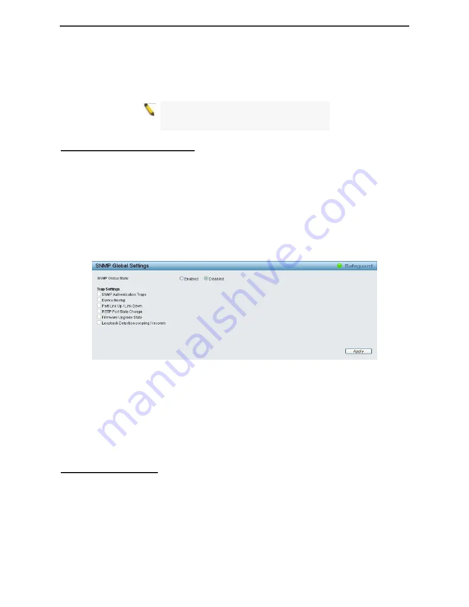
The default SNMP global state is disabled. Select Enable and click 

Apply

 to enable the SNMP function. 


Figure 4.116 – SNMP > SNMP > SNMP Global Settings 


Trap Settings: 

Specifies whether the device can send SNMP notifications.


SNMP Authentication Traps: 

Specifies the device to send authentication failure notifications.


Device Bootup: 

System boot-up information. 

Illegal Login: 

Events of incorrect password logins, recording the IP of the originating PC. 

Port Link Up / Link Down:

 Copper port connection information. 

RSTP Port State Change: 

Events of a RSTP port state changes. 

Firmware Upgrade State: 

Information of firmware upgrade - success or failure. 


SNMP > SNMP > SNMP User 

This page is used to maintain the SNMP user table for the use of SNMPv3. SNMPv3 allows or restricts users 
using the MIB OID, and also encrypts the SNMP messages sent out between users and Switch. 

Summary of Contents for DGS-1228P

Page 1: ......

Page 2: ...gging in the AC Power Cord with Power Cord Clip 7 Power Failure 10 3 Getting Started 11 Management Options 11 Using Web based Management 11 Supported Web Browsers 11 Connecting to the Switch 11 Login Web based Management 12 Smart Wizard 12 Web based Management 12 D Link Network Assistant DNA 12 4 Configuration 14 Smart Wizard Configuration 14 IP Information 14 Password 14 SNMP 15 Web based Managem...

Page 3: ...st 35 VLAN Auto Surveillance VLAN Settings 35 L2 Functions Jumbo Frame 36 L2 Functions Port Mirroring 36 L2 Functions Loopback Detection 37 L2 Functions MAC Address Table Static MAC 37 L2 Functions MAC Address Table Dynamic Forwarding Table 38 L2 Functions Spanning Tree STP Global Settings 38 L2 Functions Spanning Tree STP Port Settings 39 L2 Functions Link Aggregation Port Trunking 41 L2 Function...

Page 4: ...ite List 64 Security Smart Binding Black List 64 AAA RADIUS Server 65 AAA 802 1X 802 1X Global Settings 66 AAA 802 1X 802 1X Port Settings 66 AAA 802 1X 802 1X User 67 ACL ACL Wizard 68 ACL ACL Access List 75 ACL ACL Access Group 76 ACL ACL Hardware Resource Status 77 PoE PoE Global Settings DGS 1210 28P only 77 PoE PoE Port Settings DGS 1210 28P only 78 SNMP SNMP SNMP Global Settings 79 SNMP SNMP...

Page 5: ... save 96 debug info 97 Appendix A Ethernet Technology 98 Gigabit Ethernet Technology 98 Fast Ethernet Technology 98 Switching Technology 98 Appendix B Technical Specifications 99 Hardware Specifications 99 Key Components Performance 99 Port Functions 99 Physical Environment 99 Emission EMI Certifications 99 Safety Certifications 99 Features 99 L2 Features 99 VLAN 99 QoS Quality of Service 99 Secur...

Page 6: ...lnet Terms Usage In this guide the term Switch first letter capitalized refers to the Smart Switch and switch first letter lower case refers to other Ethernet switches Some technologies refer to terms switch bridge and switching hubs interchangeably and both are commonly accepted for Ethernet switches A NOTE indicates important information that helps a better use of the device A CAUTION indicates ...

Page 7: ... with VLAN and 802 1p traffic in the network Auto Surveillance VLAN will automatically place the vedio traffic from pre defined IP surveillance devices to an assigned VLAN with higher priority so it can be separated from normal data traffic Asymmetric VLAN is implemented in these switches for a more efficient use of shared resources such as server or gateway devices Network Security D Link s innov...

Page 8: ... 27F 28F The Link Act Speed LED flashes which indicates a network link through the corresponding port Blinking indicates that the Switch is either sending or receiving data to the port When a port has an green light this indicates that the port is running on 1000M Reset Press the Reset button for 5 seconds to reset the Switch back to the default settings All previous changes will be lost CAUTION T...

Page 9: ...t the supplied AC power cable to this port DGS 1210 52 48 Port 10 100 1000Mbps plus 4 SFP Slot Web Smart Switch Front Panel Figure 1 5 DGS 1210 52 Front Panel Power LED The Power LED lights up when the Switch is connected to a power source Port Link Act Speed LED 1 48 The Link Act Speed LED flashes which indicates a network link through the corresponding port Blinking indicates that the Switch is ...

Page 10: ...1 Product Introduction D Link Web Smart Switch User Manual 5 5 Power Connect the supplied AC power cable to this port ...

Page 11: ... Installation For safe switch installation and operation it is recommended that you Visually inspect the power cord to see that it is secured fully to the AC power connector Make sure that there is proper heat dissipation and adequate ventilation around the switch Do not place heavy objects on the switch Desktop or Shelf Installation When installing the switch on a desktop or shelf the rubber feet...

Page 12: ...omised C Mechanical Loading Mounting of the equipment in the rack should be such that a hazardous condition is not achieved due to uneven mechanical loading D Circuit Overloading Consideration should be given to the connection of the equipment to the supply circuit and the effect that overloading of the circuits might have on overcurrent protection and supply wiring Appropriate consideration of eq...

Page 13: ...gure2 4 Insert Tie Wrap to the Switch B Plug the AC power cord into the power socket of the Switch Figure 2 5 Connect the power cord to the Switch C Slide the Retainer through the Tie Wrap until the end of the cord Figure 2 6 Slide the Retainer through the Tie Wrap ...

Page 14: ...the power cord and into the locker of the Retainer Figure 2 7 Circle around the power cord E Fasten the tie of the Retainer until the power cord is secured Figure 2 8 Secure the power cord F Users may now connect the AC power cord to an electrical outlet preferably one that is grounded and surge protected ...

Page 15: ...tion D Link Web Smart Switch User Manual 10 Figure 2 9 Plugging the switch into an outlet Power Failure As a precaution the switch should be unplugged in case of power failure When power is resumed plug the switch back in ...

Page 16: ...to change the IP address of your PC and it is easier to initialize multiple Smart Switches Please refer to the following installation instructions for the Web based Management and the D Link Network Assistant DNA Using Web based Management After a successful physical installation you can configure the Switch monitor the network status and display statistics using a web browser Supported Web Browse...

Page 17: ...the language of the Web based Management interface then click OK The switch supports 10 languages including English Traditional Chinese Simplified Chinese German Spanish French Italian Portuguese Japanese and Russian By default the password is admin and the language is English Figure 3 3 Logon Dialog Box Smart Wizard After a successful login the Smart Wizard will guide you through essential settin...

Page 18: ...Smart Switch User Manual 1 13 3 NOTE Please be sure to uninstall any existing DNA from your PC before installing the latest DNA For detailed explanations of the DNA functions please refer to D Link Network Assistant DNA User Guide ...

Page 19: ...e IP Information access password and SNMP Select Static DHCP or BOOTP and enter the desired new IP Address select the Netmask and enter the Gateway address then click the Next button to enter the next Password setting page No need to enter IP Address Netmask and Gateway if DHCP and BOOTP are selected The Smart Wizard is for the quick setting in IPv4 environment For IPv6 network please go to System...

Page 20: ...Enabled and then click Apply to make it effective Figure 4 3 SNMP in Smart Wizard NOTE Changing the system IP address will disconnect you from the current connection Please enter the correct IP address in the Web browser again and make sure your PC is in the same subnet with the switch See Login Web based Management for a detailed description If you want to change the settings click OK and start a...

Page 21: ...4 Configuration D Link Web Smart Switch User Manual 16 Figure 4 4 Confirm the changes of IP address in Smart Wizard ...

Page 22: ...nt functions in the Function Tree you can change all the settings in the Main Configuration Screen The main configuration screen will show the current status of your Switch by clicking the model name on top of the function tree At the upper right corner of the screen the username and current IP address will be displayed Under the username is the Logout button Click this to end this session NOTE If...

Page 23: ...pad Figure 4 8 Save Log Tool Bar Tool Menu The Tool Menu offers global function controls such as Reset Reset System Reboot Device Configuration Backup and Restore Firmware Backup and Upgrade Figure 4 9 Tool Menu Reset Provide a safe reset option for the Switch All configuration settings in non volatile RAM will be reset to factory default except for the IP address Figure 4 10 Tool Menu Reset Reset...

Page 24: ...or a saved backup settings file Click Restore after selecting the backup settings file you want to restore TFTP TFTP Trivial File Transfer Protocol is a file transfer protocol that allows you to transfer files to a remote TFTP server Specify TFTP Server IP Address with IPv4 or IPv6 address and TFTP File Name for the configuration file you want to save to restore from Click Backup to save the curre...

Page 25: ... restore CAUTION Do not disconnect the PC or remove the power cord from device until the upgrade completes The Switch may crash if the Firmware upgrade is incomplete Tool Bar Smart Wizard By clicking the Smart Wizard button you can return to the Smart Wizard if you wish to make any changes there Tool Bar Online Help The Online Help provides two ways of online support D Link Support Site will lead ...

Page 26: ...bled Storm Control Click Settings to link to Security Storm Control Default is disabled DHCP Client Click Settings to link to System System Settings Default is disabled Jumbo Frame Click Settings to link to L2 Functions Jumbo Frame Default is disabled SNMP Status Click Settings to link to SNMP SNMP SNMP Global Settings Default is disabled 802 1X Status Click Settings to link to AAA 802 1X 802 1X S...

Page 27: ...ay can be manually configured When using DHCP mode the Switch will first look for a DHCP server to provide it with an IP address including network mask and default gateway before using the default or previously entered settings By default the IP setting is static mode with IP address is 10 90 90 90 and subnet mask is 255 0 0 0 DHCP Option 12 State Speicfy the DHCP option 12 state is enabled or dis...

Page 28: ... be enabled or disabled DHCPv6 Client Specifies the DHCPv6 client to be enabled or disabled IPv6 Network Address Specifies the IPv6 Network Address NS Retransmit Time Settings NS Retransmit Time 1 3600 Specifies the NS retransmit time for IPv6 The field range is 1 3600 and default is 1 second Automatic Link Local State Settings Automatic Link Local Address Specifies the automatic link is enabled o...

Page 29: ...in the middle part of the window State Select and enter the neighbor IPv6 state here Options to choose from are All Address Static and Dynamic When the user selects address from the drop down menu the user will be able to enter an IP address in the space provided next to the state option Click Find to locate a specific entry based on the information entered Click Clear to clear all the information...

Page 30: ...nterface When connecting the Switch to end stations user have to use straight through Ethernet cables to make sure the Tx Rx pairs match up properly When connecting the Switch to other networking devices a crossover cable must be used This switch provides a configurable MDI MDIX function for users The switches can be set as an MDI port in order to connect to other hubs or switches without an Ether...

Page 31: ...ration System DHCP BOOTP Relay DHCP BOOTP Relay Global Settings User can enable and configure DHCP BOOTP Relay Global Settings on the Switch Figure 4 26 System DHCP BOOTP Relay DHCP BOOTP Relay Global Settings BOOTP Relay State This field can be toggled between Enabled and Disabled using the pull down menu It is used to enable or disable the DHCP BOOTP Relay service on the Switch The default is Di...

Page 32: ...the switch drops the packet because it is invalid In packets received from DHCP servers the relay agent will drop invalid messages Disabled When the field is toggled to Disabled the relay agent will not check the validity of the packet s option 82 fields DHCP Relay Agent Information Option 82 Policy This field can be toggled between Replace Drop and Keep by using the pull down menu It is used to s...

Page 33: ...h CPU the Option 82 is removed and the reply is sent to the DHCP Client Figure 4 28 System DHCP Local Relay Settings DHCP BOOTP Local Relay Status Specifies whether DHCP Local Relay is enabled on the device Enabled Enables DHCP Local Relay on the device Disabled Disables DHCP Local Relay on the device This is the default value Config VLAN by Configure the VLAN by VID or VLAN Name of drop down menu...

Page 34: ...ble so you can start to configure the related settings of the remote system log server then press Apply for the changes to take effect Figure 4 30 System SysLog Host Settings Server IP Address Select IPv4 or IPv6 then specify the IP address of the system log server UDP Port Specifies the UDP port to which the server logs are sent The possible range is 1 65535 and the default value is 514 Time Stam...

Page 35: ...g Settings Type Specifies the Power Saving type to be LED Shut off Port Shut off or System Hibernation LED Shut off The LED Shut off gets high priority If the user select LED Shut off the profile function will not take effect It means the LED can not be turned on after Time Profile time s up when the state is disabled On the contrary if the LED is enabled the Time Profile function will work Port S...

Page 36: ...ividual port via the IEEE802 3az EEE setting page Figure 4 33 System IEEE802 3az EEE Settings From Port To Port A consecutive group of ports may be configured starting with the selected port State Enabled or Disabled the IEEE802 3az EEE for the specified ports By default all ports are enabled Click Apply to implement changes made If the connection speed drops down from 1000M to 100M or the first l...

Page 37: ...EEE 802 1Q VLAN Configuration page provides powerful VID management functions The original settings have the VID as 1 no default name and all ports as Untagged Rename Click to rename the VLAN group Delete VID Click to delete the VLAN group Add New VID Click to create a new VID group assigning ports from 01 to 28 as Untag Tag or Not Member A port can be untagged in only one VID To save the VID grou...

Page 38: ...VLAN page before you can assign a dedicated Voice VLAN The member port you configured in 802 1Q VLAN setting page will be the static member port of voice VLAN To dynamically add ports into the voice VLAN please enable the Auto Detection function Priority The 802 1p priority levels of the traffic in the Voice VLAN Aging Time 1 120 Enter a period of time in hours to remove a port from the voice VLAN...

Page 39: ...d not impacted by the QoS feature Note It is recommended setting the highest priority for Voice VLAN to guarantee the quality of VoIP traffic VLAN Voice VLAN Voice VLAN Port Settings The Voice VLAN Port Settings page allows users to automatically place the voice traffic from IP phone to an assigned VLAN to enhance the VoIP service With a higher priority and individual VLAN the quality and the secu...

Page 40: ...eillance VLAN is a feature that allows you to automatically place the video traffic from D Link IP cameras to an assigned VLAN to enhance the IP surveillance service With a higher priority and individual VLAN the quality and the security of surveillance traffic are guaranteed The Auto Surveillance VLAN function will check the source MAC address VLAN ID on the incoming packets If it matches specifi...

Page 41: ...create a new surveillance component and Refresh to refresh the Auto Surveillance VLAN summary table L2 Functions Jumbo Frame D Link Gigabit Web Smart Switches support jumbo frames frames larger than the Ethernet frame size of 1536 bytes of up to 9216 bytes tagged Default is disabled Select Enabled then click Apply to turn on the jumbo frame support Figure 4 43 L2 Functions Jumbo Frame L2 Functions...

Page 42: ...ll member VLANs If VLAN based mode is selected only the member port in the loop happening VLAN will be shut down VID List Specifies the VID Interval 1 32767 Set a Loop detection Interval between 1 and 32767 seconds The default is 2 seconds Recover Time 0 or 60 1000000 Time allowed in seconds for recovery when a Loopback is detected The Loop Detection Recover Time can be set at 0 seconds or 60 to 1...

Page 43: ... Switch implements two versions of the Spanning Tree Protocol the Rapid Spanning Tree Protocol RSTP as defined by the IEEE 802 1w specification and a version compatible with the IEEE 802 1D STP RSTP can operate with legacy equipment implementing IEEE 802 1D However the advantages of using RSTP will be lost The IEEE 802 1w Rapid Spanning Tree Protocol RSTP evolved from the 802 1D STP standard RSTP ...

Page 44: ...ions of configuration messages by the root device thus stating that the Switch is still functioning The default is 2 seconds Forward Delay 4 30 sec This sets the maximum amount of time that the root device will wait before changing states The default is 15 seconds Root Bridge Displays the MAC address of the Root Bridge Root Cost Display the cost of the Root Bridge Root Maximum Age Displays the Max...

Page 45: ... edge port normally should not receive BPDU packets If a BPDU packet is received it automatically loses edge port status Selecting the False parameter indicates that the port does not have edge port status Selecting the Auto parameter indicates that the port have edge port status or not have edge port status automatically Priority Specify the priority of each port Selectable range is from 0 to 240...

Page 46: ... the Switch The user may set which ports will be active and passive in processing and sending LACP control frames Figure 4 51 L2 Functions Link Aggregation LACP Port Settings From Port The beginning of a consecutive group of ports may be configured starting with the selected port To Port The ending of a consecutive group of ports may be configured starting with the selected port Activity There are...

Page 47: ... the expected packet loss on a subnet If a subnet is expected to be lossy the Robustness Variable may need to be increased The Robustness Variable cannot be set to zero and it SHOULD NOT be Default is 2 seconds Query Interval 60 600 sec The Query Interval is the interval between General Queries sent By adjusting the Query Interval the number of IGMP messages can be increased or decreased larger va...

Page 48: ...fied entry or click Delete All to remove all entries L2 Functions Multicast MLD Snooping Multicast Listener Discovery MLD Snooping is an IPv6 function used similarly to IGMP snooping in IPv4 It is used to discover ports on a VLAN that are requesting multicast data Instead of flooding all ports on a selected VLAN with multicast traffic MLD snooping will only forward multicast data to ports that wis...

Page 49: ...e Default is 2 seconds Last Member Query Interval 1 25 sec The Last Member Query Interval is the Max Response Time inserted into Group Specific Queries sent in response to Leave Group messages and is also the amount of time between Group Specific Query messages This value may be adjusted to modify the leave latency of network A reduced value results in reduced time to detect the loss of the last m...

Page 50: ...ng page displays all of the entries made into the Switch s static multicast forwarding table To implement the Multicast Forwarding Settings input VID Multicast MAC Address and port settings then click Add Figure 4 57 L2 Functions Multicast Multicast Forwarding VID The VLAN ID of the VLAN to which the corresponding MAC address belongs Multicast MAC Address The MAC address of the static source of mu...

Page 51: ...s SNTP Time Settings SNTP or Simple Network Time Protocol is used by the Switch to synchronize the clock of the computer The SNTP settings folders contain two windows Time Settings and TimeZone Settings Users can configure the time settings for the switch and the following parameters can be set or are displayed in the Time Settings page Figure 4 59 L2 Functions SNTP Time Settings Clock Source Spec...

Page 52: ...r disable the DST Settings Daylight Saving Time Offset Use this drop down menu to specify the amount of time that will constitute your local DST offset 30 60 90 or 120 minutes Time Zone Offset GMT HH MM Use these drop down menus to specify your local time zone s offset from Greenwich Mean Time GMT Daylight Saving Time Settings From Month Day Enter the month DST and date DST will start on each year...

Page 53: ...frame transmissions initiated by value or status changes in the LLDP local systems MIB The value for txDelay is set by the following range formula 1 txDelay 0 25 msgTxInterval The default value is 2 seconds L2 Functions LLDP LLDP MED Settings DGS 1210 28P Only LLDP MED Link Layer Discovery Protocol Media Endpoint Discovery is an enhancement of LLDP It improves the LLDP operation between endpoint d...

Page 54: ...stem Description Specifies whether the System Description TLV is enabled on the port The possible field values are Enabled Enables the System Description TLV on the port Disabled Disables the System Description TLV on the port System Capabilities Specifies whether the System Capabilities TLV is enabled on the port The possible field values are Enabled Enables the System Capabilities TLV on the por...

Page 55: ...ses the Power via MDI implementations supported by the port The possible field values are Enabled Enables the Power via MDI configured on the port Disabled Disables the Power via MDI configured on the port Link Aggregation Specifies whether the link aggregation is enabled on the port The possible field values are Enabled Enables the link aggregation configured on the port Disabled Disables the lin...

Page 56: ...lick Apply to implement changes made L2 Functions LLDP LLDP Management Address Table The LLDP Management Address Table page displays the detailed management address information for the entry Figure 4 67 L2 Functions LLDP LLDP Management Address Table Management Address Select IPv4 or IPv6 address and enter the IP address Click Search and the table will update and display the values required Subtyp...

Page 57: ...rt number Port ID Subtype Displays the port ID subtype Port ID Displays the port ID Unit number Port number Port Description Displays the port description Click View of Normal column to display more information Figure 4 69 L2 Functions LLDP LLDP Local Port Normal Table Click View of Detailed column to display detail information ...

Page 58: ...ions LLDP LLDP Remote Port Table This LLDP Remote Port Table page is used to display the LLDP Remote Port Brief Table Select port number and click Search to display additional information Figure 4 71 L2 Functions LLDP LLDP Remote Port Table To view the settings for a remote port click View Normal and the following page displays ...

Page 59: ...LDP Remote Port Normal Table To view the detail settings for a remote port click View Detailed and the following page displays Figure 4 73 L2 Functions LLDP LLDP Remote Port Detailed Table L2 Functions LLDP LLDP Statistics The LLDP Statistics page displays an overview of all LLDP traffic ...

Page 60: ...lays the total number of LLDP frames transmitted on the port RxPort FramesDiscarded Displays the total discarded frame number of LLDP frames received on the port RxPort FramesErrors Displays the Error frame number of LLDP frames received on the port RxPort Frames Displays the total number of LLDP frames received on the port RxPortTLVsDiscarded Each LLDP frame can contain multiple pieces of informa...

Page 61: ... port The value is between 64 and 1024000 Click Apply to set the bandwidth control for the selected ports QoS 802 1p DSCP ToS QoS is an implementation of the IEEE 802 1p standard that allows network administrators to reserve bandwidth for important functions that require a larger bandwidth or that might have a higher priority such as VoIP voice over Internet Protocol web browsing applications file...

Page 62: ...d host Otherwise you may lose the connection Figure 4 77 Security Trusted Host Trusted Host Specify the Trusted Host to be enabled or disabled The default is disabled To define a management station IP setting click the Add button and type in the IP address and Subnet mask Click the Apply button to save your settings You may permit only single or a range of IP addresses by different IP mask setting...

Page 63: ...igure traffic segmentation specify a port or All ports from the switch using the From Port pull down menu and select To Port then click Apply to enter the settings into the Switch s Traffic Segmentation table Click Select All button to check all ports or click Clear button to uncheck all ports Security Safeguard Engine D Link s Safeguard Engine is a robust and innovative technology that automatica...

Page 64: ...ing an attacker to sniff data frames on a LAN modifying the traffic or stopping the traffic known as a Denial of Service DoS attack The main idea of ARP spoofing is to send fake or spoofed ARP messages to an Ethernet network It associates the attacker s or random MAC address with the IP address of another node such as the default gateway Any traffic meant for that IP address would be mistakenly re...

Page 65: ...ecurity feature that provides a secure communication path between a Web Management host and the Switch Web UI by using authentication digital signatures and encryption These security functions are implemented by Ciphersuite a security string that determines the cryptographic parameters encryption algorithms and key sizes This page allows you to configure the SSL global state and the Ciphersuite se...

Page 66: ...ch The default is Disabled Max Session 1 4 Enter a value between 1 and 4 to set the number of users that may simultaneously access the Switch The default setting is 1 Connection Timeout 120 600 Allows the user to set the connection timeout The use may set a time between 120 and 600 seconds The default setting is 120 seconds Authfail Attempts 2 20 Allows the Administrator to set the maximum number ...

Page 67: ... enable the supports of hash for message Authentication Code HMAC MD5 Message Digest MD5 mechanism HMAC SHA1 Use the check box to enable the supports of hash for message Authentication Code HMAC Secure Hash Algorithm SHA mechanism Public Key Algorithm HMAC RSA Use the check box to enable the supports of Hash for Message Authentication Code HMAC mechanism utilizing the RSA encryption algorithm Clic...

Page 68: ... Snooping on the Switch Figure 4 89 Security Smart Binding Smart Binding Settings The Smart Binding Settings page contains the following fields From Port To Port Select a range of ports to set for IP MAC port binding State Use the drop down menu to enable or disable these ports for Smart Binding Enabled Enable Smart Binding with related configurations to the ports Disabled Disable Smart Binding Pa...

Page 69: ...ces Click Scan and the search results will be listed in below table Binding check the box to select desired binding devices Apply click Apply to set IP MAC Port Binding entries Select All to check the boxes of Binding for all found devices Clear All to cancel the box of Binding Security Smart Binding White List When IP ARP Inspection Mode is selected the White List page displays finished IP MAC Po...

Page 70: ...2 or 3 IP Address Select IPv4 or IPv6 and enter the IP address Authentication Port 1 65535 Set the RADIUS authentic server s UDP port The default port is 1812 Accounting Port 1 65535 Set the RADIUS account server s UDP port The default port is 1813 Timeout 1 255 sec This field will set the time the Switch will wait for a response of authentication from the user The user may set a time between 1 an...

Page 71: ...her depending on the configuration of the client software and the RADIUS server Depending on the authenticated results the port is either made available to the user or the user is denied access to the network Figure 4 94 AAA 802 1x Global Settings Authentication State Specify to enable or disable the 802 1X function Forward EAPOL PDU This is a global setting to control the forwarding of EAPOL PDU ...

Page 72: ... 3600 seconds Port Control This allows user to control the port authorization state Select ForceAuthorized to disable 802 1X and cause the port to transition to the authorized state without any authentication exchange required This means the port transmits and receives normal traffic without 802 1X based authentication of the client If ForceUnauthorized is selected the port will remain in the unau...

Page 73: ...The ACL Configuration Wizard will aid with the creation of access profiles and ACL Rules The ACL Wizard will create the access rule and profile automatically The maximum usable profiles are 50 and with 200 Rules in total for the switch To create a new access rule select Create and enter the Access List Name then click Next button Figure 4 97 ACL ACL Wizard Create Access List The steps of adding an...

Page 74: ...e MAC mask e g FF FF FF FF FF FF Destination Select the destination MAC to be specified or Any Enter a destination MAC address and destination MAC mask e g FF FF FF FF FF FF If user selects the 802 1Q VLAN box then need to specify the dot1p and VLAN ID Dot1p 0 7 Specify the dot1p priority VLAN ID Selecting this option instructs the Switch to examine the 802 1p priority value of each packet header ...

Page 75: ...a source IP address and source IP mask For example to set 176 212 XX XX use mask 255 255 0 0 Destination Select the destination IP to be specified or Any relevant to the ACL rules Enter a destination IP address and destination IP mask For example to set 176 212 XX XX use mask 255 255 0 0 Protocol Check Protocol to configure the related settings Protocol Type Select the protocol type for IPv4 The p...

Page 76: ...4 ACL TCP Rule Select IPv4 ACL with TCP and click Next button The updates to show the follows Figure 4 102 Add Access Rule IPv4 TCP IPv4 Address Defines the range of source Ports relevant to the ACL rules Source Defines the range of source Ports relevant to the ACL rules For example to set 0 15 set mask of FFF0 Destination Defines the range of destination IP addresses relevant to the ACL rules For...

Page 77: ...e Defines the range of source Ports relevant to the ACL rules For example to set 0 15 set mask of FFF0 Destination Defines the range of destination IP addresses relevant to the ACL rules For example to set 0 15 set mask of FFF0 Click Next button then the ACL profile is added NOTE A combination of one or several filtering masks can be selected simultaneously The page updates with the relevant field...

Page 78: ...s For example to set 2002 0 0 0 0 0 b0d4 0 use mask 128 Destination IPv6 Address Defines the range of destination IP addresses relevant to the ACL rules For example to set 2002 0 0 0 0 0 bfd4 0 use mask 128 Action Specify the ACL forwarding action matching the rule criteria Permit forwards packets if all other ACL criteria are met Deny drops packets if all other ACL criteria is met Click Next butt...

Page 79: ...d To define the IPv6 ACL UDP profile Select IPv6 ACL with UDP of Protocol Type and click Next button The updates to show the follows Figure 4 106 Add Access Rule IPv6 UDP Source Port Specify the source port Source Port Mask Defines the range of source IP addresses relevant to the ACL rules For example to set 0 15 set mask of FFF0 Destination Port Specify the destination port Destination Port Mask ...

Page 80: ...g rule please select Update and the Access List Name hyperlink and click Next button Figure 4 108 ACL ACL Wizard Update ACL List ACL ACL Access List The ACL Access List page provides information for configuring ACL Access manually Click Edit Rules button to modify the access profile or click Delete button to remove the ACL profile Figure 4 109 ACL ACL Access List ...

Page 81: ...fy the packet type to be MAC IPv4 IPv4 Exdended or IPv6 then click Apply button To modify an existing rule please click on the Sequence No hyperlink Figure 4 111 ACL ACL Access List Update ACL Profile ACL ACL Access Group The ACL Access Group page allows user to configure the ACL access group settings Figure 4 112 ACL ACL Access Group Port Specify the ports to be added in the access list group MAC...

Page 82: ... Threshold Manually configure the system power budget 7 1 193 0 watts for DGS 1210 28P Power Shut Off Sequence Defines the method used to deny power to a port once the threshold is reached The possible fields are Deny next port When the power budget is exceeded the next port attempting to power up is denied regardless of the port priority Deny low priority port The port with the lower priority wil...

Page 83: ...the ports if port current is over 375mA in 802 3af mode or 625mA in pre 802 3at mode Note The PoE Status information of Power current Power Voltage and Current is the power usage information of the connected PD please Refresh to renew the information Figure 4 115 PoE PoE Port Setting From Port To Port Specifies the PoE function of a port or ports State Select Enabled or Disabled to configure PoE f...

Page 84: ... managed objects is maintained by the SNMP agent and used to manage the device These objects are defined in a Management Information Base MIB which provides a standard presentation of the information controlled by the on board SNMP agent SNMP defines both the format of the MIB specifications and the protocol used to access this information over the network The default SNMP global state is disabled...

Page 85: ...f up to 32 characters Read View Name Specify a SNMP group name for users that are allowed SNMP read privileges to the Switch s SNMP agent Write View Name Specify a SNMP group name for users that are allowed SNMP write privileges to the Switch s SNMP agent Security Model Select the SNMP security model SNMPv1 SNMPv1 does not support the security features SNMPv2 SNMPv2 supports both centralized and d...

Page 86: ... concerned For example 1 3 6 1 2 1 1 with mask 1 1 1 1 1 1 0 means 1 3 6 1 2 1 X View Type Specify the configured OID is Included or Excluded that a SNMP manager can access Click Add to create a new view Delete to remove an existing view SNMP SNMP SNMP Community This page is used to maintain the SNMP community string of the SNMP managers using the same community string are permitted to gain access...

Page 87: ...ult value Figure 4 122 SNMP SNMP SNMP Engine ID SNMP RMON RMON Global Settings Users can enable and disable remote monitoring RMON status for the SNMP function on the Switch In addition RMON Rising and Falling Alarm Traps can be enabled and disabled Click Apply to make effects Figure 4 123 SNMP RMON RMON Global Settings SNMP RMON RMON Statistics The RMON Statistics Configuration page displays the ...

Page 88: ...tation or user that requested the RMON information Click Apply to make the configurations take effects SNMP RMON RMON Alarm Settings The RMON Alarm Settings page allows the user to configure the network alarms Network alarms occur when a network problem or event is detected Figure 4 126 SNMP RMON RMON Alarm Settings The configuration contains the following fields Index 1 65535 Indicates a specific...

Page 89: ...nt Description Specifies the user defined event description Type Specifies the event type The possible values are None Indicates that no event occurred Log Indicates that the event is a log entry SNMP Trap Indicates that the event is a trap Log and Trap Indicates that the event is both a log entry and a trap Community Specifies the community to which the event belongs Owner Specifies the time that...

Page 90: ...e cable diagnostic results OK means the cable is good for the connection Short in Cable means the wires of the RJ45 cable may be in contact somewhere Open in Cable means the wires of RJ45 cable may be broken or the other end of the cable is simply disconnected Test Failed means some other errors occurred during cable diagnostics Please select the same port and test again Cable Fault Distance meter...

Page 91: ...hen sessions timed out as well as other system information Figure 4 131 Monitoring System Log ID Displays an incremented counter of the System Log entry The Maximum entries are 500 Time Displays the time in days hours and minutes the log was entered Log Description Displays a description event recorded Severity Displays a severity level of the event recorded Click Refresh to renew the page and cli...

Page 92: ...ve Press Enter in both the Username and Password fields The command prompt will appear as shown below DGS 1210 28 DGS 1210 28 login admin Password DGS 1210 28 Figure 5 1 Command Prompt The user session is automatically terminated if idle for the login timeout period The default login timeout period is 5 minutes To change the login timeout session please refer to chapter 5 CLI Commands The Basic Sw...

Page 93: ...tch DGS 1210 28 USEREXEC commands config account admin password passwd config ipif System ipaddress ip address subnet mask gateway gw address dhcp debug info download firmware_fromTFTP tftp ip address filename cfg_fromTFTP tftp ip address filename logout ping ip_addr reboot reset config save show ipif show switch upload firmware_toTFTP tftp ip address filename cfg_toTFTP tftp ip address filename D...

Page 94: ...uration file on the TFTP server You need to specify the DOS path if the file is not at the root directory of the TFTP server Restrictions None Example usage To download a firmware file DGS 1210 28 download firmware_fromTFTP 1 1 1 23 1 dgs_1210 10032 ros 01 Jan 2000 01 19 48 COPY I FILECPY Files Copy source URL tftp 1 1 1 23 1 dgs_1210 10032 ros destination URL Unit all flash image 01 Jan 2000 01 2...

Page 95: ...PY Files Copy source URL running config destination URL tftp 1 1 1 23 1 running config 01 Jan 2000 01 26 16 COPY W TRAP The copy operation was completed success fully 158 bytes copied in 00 00 05 hh mm ss DGS 1210 28 config ipif system Purpose To configure the System IP interface Syntax config ipif system ipaddress ip address subnet mask gateway gw address dhcp bootp Description The config ipif sy...

Page 96: ...tiple IPv6 addresses can be configured for a single IP interface Ex 3ffe 501 ffff 100 1 64 The 64 represents the prefix length of the IPv6 addresses dhcpv6_client enable disable Specify the DHCPv6 client to be disabled or enabled Restrictions None Example usage To configure the IPv6 interface System DGS 1210 28 config ipif System ipv6 ipv6address 3ffe 501 ffff 100 1 64 Success DGS 1210 28 logout P...

Page 97: ...eceived From 10 90 90 91 TimeTaken 20 msecs 10 90 90 91 Ping Statistics 3 Packets Transmitted 3 Packets Received 0 Packets Loss DGS 1210 28 ping6 Purpose To test the connectivity between network devices Syntax ping6 ipv6addr Description The pingv6 command checks if another IP address is reachable on the network You can ping the IP address connected to through the managed VLAN VLAN 1 by default as ...

Page 98: ...static address 10 90 90 92 to the routing table DGS 1210 28 create iproute default 10 90 90 92 Command create iproute default 10 90 90 92 Success DGS 1210 28 delete iproute Purpose Used to delete an IP route entry from the Switch s IP routing table Syntax delete iproute default Description The delete iproute command will delete an existing IP route entry from the Switch s IP routing table Paramete...

Page 99: ... Purpose To reboot the Switch If the Switch is a member of a stack it may be rebooted individually without affecting the other members of the stack Syntax reboot Description The reboot command reboots the system All network connections are terminated and the boot code executes Parameters None Restrictions None Example usage To restart the Switch DGS 1210 28 reboot Device will reboot please wait a ...

Page 100: ...he switch Parameters None Restrictions None Example usage To display IP interface settings DGS 1210 28 show ipif IP Setting Mode Static IP Address 10 90 90 90 Subnet Mask 255 0 0 0 Default Gateway 0 0 0 0 DHCPv6 Client State Disabled IPv6 Global Unicast Address 3ffe 501 ffff 100 100 1 64 DGS 1210 28 show switch Purpose To display information about the Switch Syntax show switch Description The show...

Page 101: ...face on the Switch Syntax config account admin password passwd Description The config account admin password command sets the administrator password Parameters passwd The new password of the administrator Restrictions None Example usage To configure the account admin password DGS 1210 28 config account admin password 1234 DGS 1210 28 save Purpose To save changes in the Switch s configuration to no...

Page 102: ...strictions None Example usage To display the ARP table and MAC FDB information of the Switch DGS 1210 28 debug info segmentation fault log file File doesn t exist ARP table Address Hardware Address Type Interface Mapping 10 90 90 90 00 18 8b bf 75 30 ARPA vlan1 Static 10 90 90 98 00 19 5b 14 3d c4 ARPA vlan1 Dynamic 10 255 255 255 ff ff ff ff ff ff ARPA vlan1 Static MAC table Vlan Mac Address Type...

Page 103: ... unshielded twisted pair UTP cabling a flexible foundation for the next generation of network technology products will be created This will outfit your network with a powerful 1000 Mbps capable backbone server connection Fast Ethernet Technology The growing importance of LANs and the increasing complexity of desktop computing applications are fueling the need for high performance networks A number...

Page 104: ... 331R 1000Base BX TX 1310 RX 1550nm 40km Physical Environment AC input 100 240 VAC 50 60Hz internal universal power supply Acoustic Value 0dB Fan less Operation Temperature 5 50 C Storage Temperature 20 70 C Operation Humidity 0 95 RH Storage Humidity 0 95 RH Emission EMI Certifications FCC class A CE Class A VCCI Class A IC Class A Safety Certifications cUL LVD CE Features L2 Features Supports up...

Page 105: ...HCP Snooping OAM Cable Diagnostics Reset button reset to factory default Management Web based GUI or D Link Network Assistant DNA D Link CLI style SNMP support DHCP client Trap setting for destination IP system events fiber port events twisted pair port events Password access control Web based configuration backup restoration Web based firmware backup restore Firmware upgrade using D Link Network ...

Page 106: ...tion of the equipment in a rack should be such that the amount of air flow required for safe operation of the equipment is not compromised C Mechanical Loading Mounting of the equipment in the rack should be such that a hazardous condition is not achieved due to uneven mechanical loading D Circuit Overloading Consideration should be given to the connection of the equipment to the supply circuit an...

Page 107: ......

Reviews: