background image

DCM-200 USB/Ethernet Cable Modem 


5

Identifying External Components 

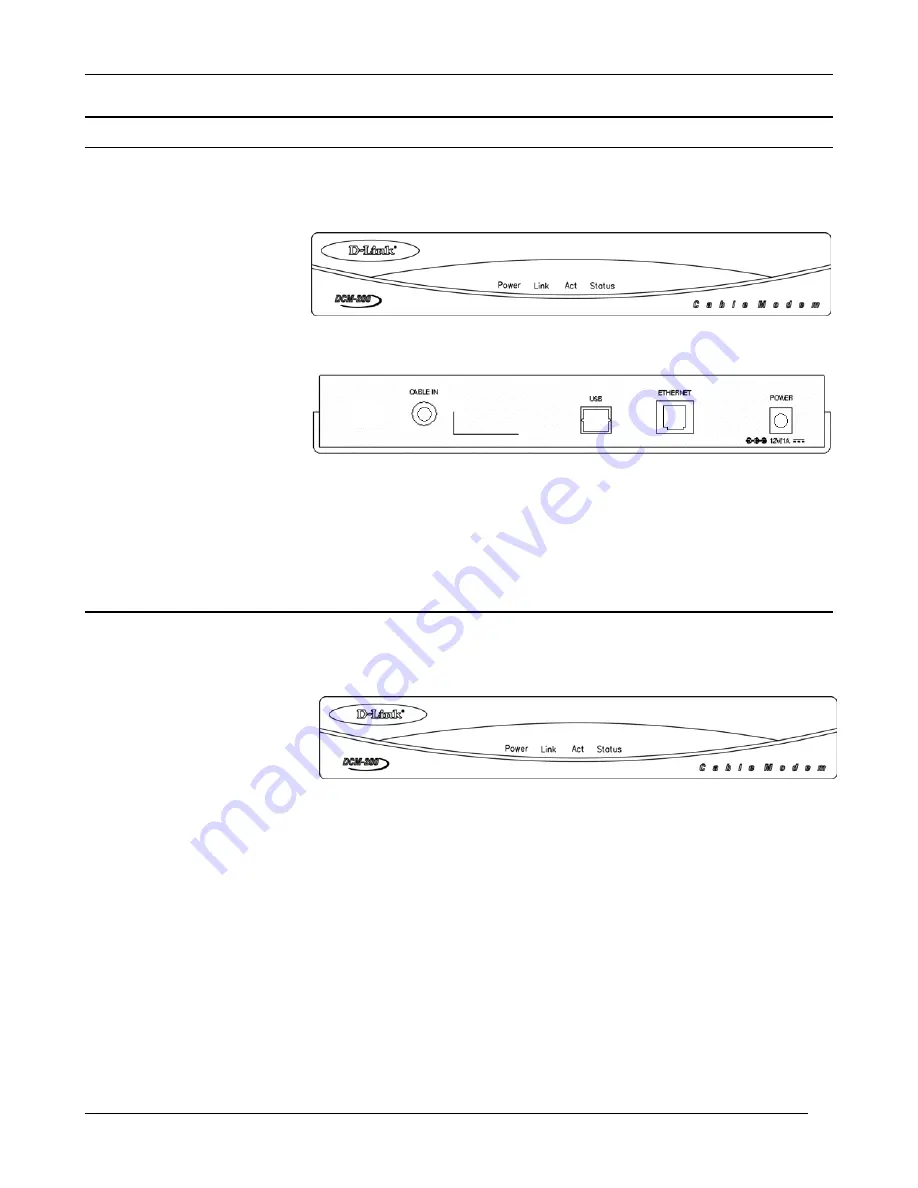
This section identifies all the major external components of the device. Both the front and rear panels are shown 

below followed by a description of each panel feature. The indicator panel is described in detail in the following 

section. 

Front Panel 

This figure shows the front 

panel of the device.  


LED Indicator Panel Refer to the next chapter, “

Understanding Indicators

,” for detailed information about 

each of the DCM-200’s LED indicators. 

Rear Panel 

This figure shows the rear 

panel of the device. 
 

AC Power Connector - For the included power adapter, if you use a power adapter other than the one included 

with the product, please make sure it has a DC output of 12V/1A. 

Ethernet 10BASE-T Port - The 10BASE-T Ethernet port accepts Category 5 or better UTP cabling with an RJ-

45 connector used to connect the DCM-100 to a LAN device (hub, switch, PC, etc.). 

Cable In This jack is used to connect the DCM-200 to the splitter. This connection is achieved using a length of 

cable TV wire supplied by your cable company during installation. 

USB Port Connect this port on the DCM-200 directly to your PC. 

Understanding Indicators 

Before setting up your 

USB/Ethernet Cable Modem for 

the first time, take a few minutes 

to look over this section and 

familiarize yourself with the 

front panel LED indicators 

depicted below. 

Power

 - This LED is lit red when the device is receiving power; otherwise, it is unlit. 

Link

 - This LED is lit green to indicate that a valid connection exists between the Ethernet port on the Cable 

Modem and your PC. If it is unlit, there is no valid connection.   


Act (Activity)

 - A blinking green LED indicates that traffic activity is passing through your cable modem 

port. 

Status

 – The Status LED will be “ON” solid when the cable modem is properly connected to the cable network 

(ISP). *If your status light continues to blink, please contact your cable operator for further instructions.  

NOTE:

    If no lights come, check all of your connection to see if they are properly inserted. 

Powering Up the First Time 

You must allow at least 1 to 3 minutes to power up the first time because the DCM-200 must find and secure a 

connection. 


Summary of Contents for DCM-200

Page 1: ...DCM 200 DOCSIS 1 0 DOCSIS 1 1 Upgradable USB Ethernet Cable Modem Manual Third Edition Dec 2001 6DCM200 04 Made in Taiwan RECYCLABLE...

Page 2: ...____________________ 3 Local Cable Service 3 Minimum System Requirements 3 Connection Architecture 4 Identifying External Components _________________________________________________________________ 5...

Page 3: ...face and a standard RJ 45 port for a 10BASE T connection to a computer or computer network When properly configured these connections allow simultaneous data transfers to an existing IP data network o...

Page 4: ..._________________ Serial Number ________________________________________________ Minimum System Requirements The capabilities and limitations of your computer equipment and configuration can affect th...

Page 5: ...out of the splitter can be connected to your TV or set top box and the cable modem NOTE 1 If your cable TV company does not provide a splitter or you chose to buy your own make sure you get one with s...

Page 6: ...ction is achieved using a length of cable TV wire supplied by your cable company during installation USB Port Connect this port on the DCM 200 directly to your PC Understanding Indicators Before setti...

Page 7: ...ce The DCM 200 USB Ethernet Cable Modem can only work with either the Ethernet port or the USB port at one time They CANNOT work simultaneously If you connect both the USB port and Ethernet port to di...

Page 8: ...ple near a bathtub toilet or sink Placement Do not place this product on an unstable surface The product may fall causing serious injury to a child or adult as well as serious damage to the product Di...

Page 9: ...coming from the central office Report the problem to your cable operator if the cable connection appears to be OK LED indicators appear to be normal but Internet access can not be established Try to e...

Page 10: ...mV QPSK Error Correction Reed Solomon Interface CPE Interface 10BASE T Ethernet RJ45 RF Interface F Type Female 75 ohm connector USB Interface USB 1 0 compliant Type B receptacle LEDs Power Link Act S...

Page 11: ...ants that during the Warranty Period the magnetic media on which D Link delivers the Software will be free of physical defects D Link s sole obligation shall be to replace the non conforming Software...

Page 12: ...IS REPAIR REPLACEMENT OR REFUND OF THE DEFECTIVE OR NON CONFORMING PRODUCT GOVERNING LAW This 5 Year Warranty shall be governed by the laws of the state of California Some states do not allow exclusi...

Reviews: